|
Dla tego produktu nie napisano jeszcze recenzji!
 ;
Instrukcja bardzo czytelna. zawiera co potrzeba. Polecam
 ;
...instrukcja serwisowa w pełni czytelna i kompletna. Dziękuję!
;
Instrukcja Serwisowa jest kompletna i czytelna. Dziękuję!
;
Wszystko OK!
Dokumentacja jest czytelna.
Dziękuję.
;
Bardzo dobra jakość skanu, przystępna cena. Instrukcja serwisowa okazała się przydatna przy "reanimowaniu" dwudziestoparoletniego decka, który teraz pięknie gra :)
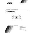
AX-M9000 Removing the current mode source selector board assembly and rear terminal panel (See Fig. 16)
Prior to performing the following procedure, remove the metal cover and the rear panel. 1. Remove the six screws W attaching the RCA pins on the current mode source selector board assembly. Then, the current mode source selector board can be removed. 2. Remove the four screws X attaching the cannon connector on the signal processing board.
Rear terminal panel Current mode source selector board assembly
W
3. Then, the rear terminal panel can be removed.
X
Fig.16
Y
Removing the signal processing board assembly (See Fig. 17)
Prior to performing the following procedure, remove the metal cover and the rear panel. 1. Remove the current mode source selector board assembly and the rear terminal panel. 2. Remove the five screws Y attaching the signal processing board assembly. 3. Remove the connectors CN251 and CN252.
Y
Signal processing board
Fig.17
Removing the power switch board assembly (See Fig. 18)
Prior to performing the following procedure, remove the metal cover. 1. Remove the four screws Z attaching the power switch board assembly. 2. Remove the cable connecting to the transformer.
Z
Power switch board
Fig.18 1-7
|