|
|
|
Kategorie
|
|
Informacje
|
|
Polecamy
|
|
|
 |
|
|
Dla tego produktu nie napisano jeszcze recenzji!
 ;
Wszystko w porządku.
Instrukcja czytelna i kompletna.
Dziękuję.
all right!
thank you.
;
Bardzo dobra instrukcja. Zawiera wszystko co potrzeba, polecam!
 ;
Instrukcja jest OK. Schematy czytelne, opisane niektóre procedury.
;
Instrukcja bardzo czytelna. zawiera co potrzeba. Polecam
;
...instrukcja serwisowa w pełni czytelna i kompletna. Dziękuję!
1-2. Electrical Alignment
Preparation 1. Connect the equipment. 2. Extend the APR-30 board using the extension board EX-592. (Refer to �1-6. Use of Extension Board� in the Maintenance Manual for DSM-T1.) 3. Connect the coaxial cable and harness to the APR-30 board. Coaxial cable : CN100 (A-3) Harness (white) : CN900 (A-6) Harness (red)*1 : CN1100 (A-6)
*1 : Only when the rear panel with 5-pin XLR connector is used.
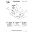
Adjustment Procedures 1. Supply 100% color-bar signal from the composite video signal generator to the VIDEO connector on the DSM-T1. 2. Adjust RV301 (B-4) on the APR-30 board so that VIDEO OUT of the DSM-R1 is satisfied the specification. Adjustment : 1RV301 (B-4) Specification : A = 700 ± 7 mV
4. Return the menu setting data of the DSM-T1 and the DSM-R1 to the factory setting. (Refer to �3. To return the menu setting data to the factory setting� on the page 1-2.) 5. Turn on the power of the DSM-T1 and warm up the unit about 10 minutes. 6. Set the following menu for DSM-T1. (Refer to the �Menu Setup� in the Operation Manual for DSM-T1.) . �03 : VIDEO STD� : 625 7. Set the following menu for DSM-R1. (Refer to the �Menu Setup� in the Operation Manual for DSM-R1.) . �03: VIDEO STD� : 625 8. Set the synthesized signal generator. . Frequency : 1270 MHz . Out Level : 0.0 dBm
A
9
1
6
5
4
8 7
3
A B C D E F G H J K L
RV301
APR-30 board (A side)
1111
2
1-6 (E)
BKSM-T103
|
|
|
> |
|