|
Dla tego produktu nie napisano jeszcze recenzji!
 ;
Dokładna dokumentacja, pomogła w szybkiej naprawie telewizora. Dziękuję!
 ;
jedyne do czego mogę mieć zastrzeżenie to jakość zdjęć zawartych w przesłanej instrukcji serwisowej ponieważ są fatalnej jakości, praktycznie nieczytelne. tak poza tym jestem zadowolony to jest to czego szukałem.
;
Wszystko w porządku.
Instrukcja czytelna i kompletna.
Dziękuję.
all right!
thank you.
;
Bardzo dobra instrukcja. Zawiera wszystko co potrzeba, polecam!
;
Instrukcja jest OK. Schematy czytelne, opisane niektóre procedury.
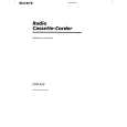
SECTION 3 DIAL POINTER SETTING
Note : Follow the instaooation procedure in the numerical order given.
1 Attach TU worm to tuner chassis. 2 Attach needle, tighten needle spring using a bolt, then attach TU
LED board. 3 Rotate TU worm until needle stops at the stopper shown in Fig. A.
2 Pointer
Screw (+P 2.6x5)
Fig. A
Retainer, Pointer
4 Plate, blind
Stopper
Fig. B
5 Knob, band
Chassis, TU
TUN LED board
4 Mount PLATE BLIND and position it as shown in Fig. B. 5 Attach the band knob. Make sure that the projected part of the
1 Worm, TU
tuner chassis fits as shown in Fig. C (the arrow).
3
Fig. C
6 Tighten idler gear, combine projected part of band knob and the
band slider so that they interlock, then mount to main board. 7 Mount VR gear to main board, then turn in the direction of the arrow until it stops. 8 Fasten the TU gear to the TU chassis with the screw.
8 Gear, TU
Screws (+BV 3x10)
Screw (+BV 3x10)
Main board
Slieder, band
Screw (+B 2.6x5)
Chassis, TU
7 Gear, VR
Screw (+BV 3x10)
6 Gear, idler
�7�
|