|
|
|
Kategorie
|
|
Informacje
|
|
Polecamy
|
|
|
 |
|
|
Dla tego produktu nie napisano jeszcze recenzji!
 ;
Schematy są ale można wysilić się i zrobić kolorowy skan i o większej rozdzielczości. Wtedy schematy płytek będą czytelniejsze. Całość super jako wartość merytoryczna. Wszystkie dane potrzebne do podłączenia różnego rodzajów urządzeń takich gramofon, CD itd.
 ;
Szybko, sprawnie i tanio. Serwis godny polecenia. Będę polecał innym
;
Ogólnie jest OK, z wyjątkiem obrazu płyty głównej, który jest miejscami mało czytelny, ale można sobie poradzić.
;
Dokładna dokumentacja, pomogła w szybkiej naprawie telewizora. Dziękuję!
;
jedyne do czego mogę mieć zastrzeżenie to jakość zdjęć zawartych w przesłanej instrukcji serwisowej ponieważ są fatalnej jakości, praktycznie nieczytelne. tak poza tym jestem zadowolony to jest to czego szukałem.
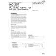
B CD C.B
TP4
1
IC404
TP3
IC401
1
SFR430
A MAIN C.B
L801
TP2
2
3
< CD SECTION >
1. Focus Bias Adjustment Make the focus bias adjustment when replacing and repairing the optical block.
Oscilloscope (DC range)
EYE PATTERN must be CLEAR and MAX VOLT / DIV: 200mV TIME / DIV: 0.5µs MAX
0V
+
TP3 (RF) TP4 (VREF)
< TAPE RECORDER SECTION >
2. Bias Adjustment � Test tape: TTA-630 � Test Point: TP2 � Adjustment location: L801 � Method: L801 .............................................................. 85kHz±2kHz 3. Azimuth Adjustment Condition: � Test tape: TTA-320 � Test point: PHONE JACK � Adjustment location: Azimuth adjustment screw Method: Play back the test tape and adjust the screw so that the output is maximum.
-
1) Connect an oscilloscope to the test point TP3 (RF) and TP4 (VREF). 2) Turn on the power switch. 3) Insert test disc TCD-782 (YEDS-18) and play back the second composition. 4) Adjust SFR430 so that RF signal of the test point TP3 (RF) is MAX and CLEAREST.
� 24 �
|
|
|
> |
|