|
|
|
Kategorie
|
|
Informacje
|
|
Polecamy
|
|
|
 |
|
|
Dla tego produktu nie napisano jeszcze recenzji!
 ;
Dokładna dokumentacja, pomogła w szybkiej naprawie telewizora. Dziękuję!
 ;
jedyne do czego mogę mieć zastrzeżenie to jakość zdjęć zawartych w przesłanej instrukcji serwisowej ponieważ są fatalnej jakości, praktycznie nieczytelne. tak poza tym jestem zadowolony to jest to czego szukałem.
 ;
Wszystko w porządku.
Instrukcja czytelna i kompletna.
Dziękuję.
all right!
thank you.
 ;
Bardzo dobra instrukcja. Zawiera wszystko co potrzeba, polecam!
 ;
Instrukcja jest OK. Schematy czytelne, opisane niektóre procedury.
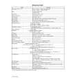
IC DESCRIPTION IC, TMP04CH00F350
Pin No. 1 2, 3 4 5 6 7 8 9 10 11 12 13 14 15 16 17 18 19 20 21 Pin Name V1 C1, C2 VSS VXT BRESET XLIN XLOUT VDD XHIN XHOUT TEST BUZZER OUT BUCK UP JOG IN1 JOG IN2 FAST KEY SET KEY SLEEP KEY SNOOZE KEY DAY KEY I/O O � � O I I O � I O I O I I I I I I I I H: JOG UP/DOWN is set to 10 minutes by one click. L: JOG UP/DOWN is set to 1 minute by one click. Sets the time, cancels the alarm and starts the date setting mode. Used to set the sleep setting and to check the remaining time. Cancels the alarm by every 5 minutes and cancels sleep. Sets and cancels the summertime. And toggles between the alarm display and date display. 22 ALARM IN 1 I H: When the ALARM mode switch is in the 1, or 1 + 2. L: When the ALARM mode switch is in the 2. 23 ALARM IN 2 I H: When the ALARM mode switch is in the 1 + 2 or 2. L: When the ALARM mode switch is in the 1. 24 ALARM IN 3 I H: When the POWER switch is in ALARM. L: When the POWER switch is in ON or STANDBY. 25 26 27 28 29 30-89 90-97 98-100 ALARM IN 4 POWER ON POWER OUT EL 24H IN S1-S60 COM1-COM8 V4-V2 I I O O I O O O H: When the ALARM function switch is in the BUZZER position. L: When the ALARM function switch is in the RADIO position. Recognizes the POWER (RADIO) ON/OFF. H: RADIO output. L: STANDBY state. When any key input (short pressing) is present, �H� is outputted for 5 seconds. Or �H� is continuously outputted when the SNOOZE key is pressed for a long time. H: 24H. L: 12H. LCD segment output. LCD common output. Stepped-up voltage output. TEST input. Outputs the buzzer signal when it reaches the alarm time. H: Normal state L: Backup mode (Power off state). See Note. Modification of the time shall be made by the JOG spec. Power supply (+). Terminal to which external crystal/resistor for high-speed oscillation is connected. Regulator-2 output. Capacitor terminal for LCD step-up voltage. Power supply (�). Regulator-1 output (It is outputted in 3.0 V type only). Reset input (active at low). Terminal to which external crystal for low speed oscillation is connected. Description
Note: In the BACKUP mode, the present time and the ALARM time setup are kept alive while the other functions are turned off (LCD is also turned off).
11
|
|
 |
> |
|


