|
Dla tego produktu nie napisano jeszcze recenzji!
 ;
Schematy są ale można wysilić się i zrobić kolorowy skan i o większej rozdzielczości. Wtedy schematy płytek będą czytelniejsze. Całość super jako wartość merytoryczna. Wszystkie dane potrzebne do podłączenia różnego rodzajów urządzeń takich gramofon, CD itd.
 ;
Szybko, sprawnie i tanio. Serwis godny polecenia. Będę polecał innym
;
Ogólnie jest OK, z wyjątkiem obrazu płyty głównej, który jest miejscami mało czytelny, ale można sobie poradzić.
;
Dokładna dokumentacja, pomogła w szybkiej naprawie telewizora. Dziękuję!
;
jedyne do czego mogę mieć zastrzeżenie to jakość zdjęć zawartych w przesłanej instrukcji serwisowej ponieważ są fatalnej jakości, praktycznie nieczytelne. tak poza tym jestem zadowolony to jest to czego szukałem.
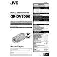
2.5 CHECKUP AND ADJUSTMENT OF MECHANISM PHASE
24 MODE GEAR
Align the MODE GEAR with the Main Deck Assembly hole. Note: The MODE GEAR may be displaced during the mechanism operation, however it can be checked from the rear and realigned during manual assembly.
27 ROTARY ENCODER
Mount the ROTARY ENCODER by aligning its mark ( and the mark ( ) of the Main Deck Assembly. Note: Be careful when handling the FPC during mounting. )
34 REEL GEAR 1
Align the REEL GEAR 1 with the Main Deck Assembly hole. Note: The REEL GEAR 1 may be displaced during mechanism operation, however this can be checked from the rear and realigned during manual assembly.
29 MAIN CAM ASSY/ 30 SLIDE ARM ASSY
When mounting the SLIDE ARM ASSY align it with the Main Deck Assembly and MAIN CAM ASSY holes. Note: During the mounting procedure, make sure that the 32 . SUB CAM ASSY is in the correct mounting position.
32 SUB CAM ASSY/ 33 CONTROL ARM ASSY
Mount the SUB CAM ASSY hole to align with the CONTROL ARM ASSY and Main Deck Assembly holes and then tighten them all together with a screw. The screw tightening torque should be 0.039 N�m (0.4 kgf�cm) Note: When mounting it, make sure that the 29 MAIN CAM ASSY is in the correct mounting position.
Fig. 2-5-1
2-14
|