|
|
|
Kategorie
|
|
Informacje
|
|
Polecamy
|
|
|
 |
|
|
Dla tego produktu nie napisano jeszcze recenzji!
 ;
Schematy są ale można wysilić się i zrobić kolorowy skan i o większej rozdzielczości. Wtedy schematy płytek będą czytelniejsze. Całość super jako wartość merytoryczna. Wszystkie dane potrzebne do podłączenia różnego rodzajów urządzeń takich gramofon, CD itd.
 ;
Szybko, sprawnie i tanio. Serwis godny polecenia. Będę polecał innym
;
Ogólnie jest OK, z wyjątkiem obrazu płyty głównej, który jest miejscami mało czytelny, ale można sobie poradzić.
;
Dokładna dokumentacja, pomogła w szybkiej naprawie telewizora. Dziękuję!
;
jedyne do czego mogę mieć zastrzeżenie to jakość zdjęć zawartych w przesłanej instrukcji serwisowej ponieważ są fatalnej jakości, praktycznie nieczytelne. tak poza tym jestem zadowolony to jest to czego szukałem.
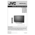
<INNER PWB SIDE> 3.1.18 AV TERMINAL BOARD � Take out the BODY COVER. (1) Remove 5 screws [ A ]. (2) Remove 1 screw [ B ]. (3) Pull out the POWER CORD CLAMP. (4) Remove the nut [ C ] attaching the ANTENNA TERMINAL. (5) Take out the AV TERMINAL BOARD. 3.1.19 SUB DRIVE PWB � Take out the BODY COVER. � Take out the BODY BRACKET. � Take out the MAIN UNIT. (1) Remove 4 screws [ D ]. (2) Take out the PWB HOLDER. (3) Disconnect the connector [CN401] and [CN402]. (4) Remove 6 screws [ E ]. (5) Take out the SUB DRIVE PWB. 3.1.20 POWER PWB � Take out the BODY COVER. � Take out the BODY BRACKET. � Take out the MAIN UNIT. (1) Remove 1 screw [ F ]. (2) Take out the POWER PWB BRACKET. (3) Disconnect the connector [CN90BL], [CN90SE], [CN90AA], [CN90B], [CN90DD] and [CN90G]. (4) Remove 5 screws [ G ]. (5) Take out the POWER PWB. 3.1.21 DIGITAL SIGNAL PWB � Take out the BODY COVER. � Take out the BODY BRACKET. � Take out the MAIN UNIT. � Take out the AV TERMINAL BOARD. � Take out the PWB HOLDER (1) Disconnect the connector [CN001], [CN002], [CN003], [CN0FC] and [CN0LV2]. (2) Remove 1 screw [ H ] attaching the earth wire. (3) Remove 1 screw [ I ]. (4) Remove the both side SHIELD COVER. (5) Take out the DIGITAL SIGNAL PWB. CAUTION: Make sure to perform the "SYSTEM SETTING" on page 1-10, when DIGITAL SIGNAL PWB is replaced.
3.1.22 RECEIVER PWB � Take out the BODY COVER. � Take out the BODY BRACKET. � Take out the MAIN UNIT. � Take out the AV TERMINAL BOARD. � Take out the PWB HOLDER (1) Remove 1 screw [ J ]. (2) Take out the ANALOG PWB BRACKET with PWB. (RECEIVER PWB / ANALOG SIGNAL PWB / REGULATOR PWB) (3) Disconnect the connector [CN10FC], [CN10PH], [CN100R], [CN10PH], [CN100A], [CN100T], [CN100F], [CN10FJ], [CN10FL], [CN10SW], [CN10AA] and [CN10SP]. (4) Remove 4 screws [ K ]. (5) Take out the RECEIVER PWB. 3.1.23 ANALOG SIGNAL PWB � Take out the BODY COVER. � Take out the BODY BRACKET. � Take out the MAIN UNIT. � Take out the AV TERMINAL BOARD. � Take out the PWB HOLDER � Take out the RECEIVER PWB. (1) Disconnect the connector [CN001], [CN002], [CN00D], [CN0J1], [CN0J2], [CN00T], [CN00F] and [CN00G]. (2) Remove 2 screws [ L ]. (3) Take out the ANALOG SIGNAL PWB. 3.1.24 REGULATOR PWB � Take out the BODY COVER. � Take out the BODY BRACKET. � Take out the MAIN UNIT. � Take out the AV TERMINAL BOARD. � Take out the PWB HOLDER � Take out the RECEIVER PWB. (1) Disconnect the connector [CN20D], [CN203] and [CN20B]. (2) Remove 4 screws [ M ]. (3) Take out the REGULATOR PWB. 3.1.25 REAR JACK PWB � Take out the BODY COVER. � Take out the BODY BRACKET. � Take out the MAIN UNIT. � Take out the AV TERMINAL BOARD. (1) Disconnect the connector [CNPH], [CNJ0J2]. (2) Remove 2 screws [ N ]. (3) Take out the REAR JACK PWB.
[CNJ0J1]
and
(No.YA092B)1-15
|
|
|
> |
|