|
|
|
Kategorie
|
|
Informacje
|
|
Polecamy
|
|
|
 |
|
|
Dla tego produktu nie napisano jeszcze recenzji!
 ;
Schematy są ale można wysilić się i zrobić kolorowy skan i o większej rozdzielczości. Wtedy schematy płytek będą czytelniejsze. Całość super jako wartość merytoryczna. Wszystkie dane potrzebne do podłączenia różnego rodzajów urządzeń takich gramofon, CD itd.
 ;
Szybko, sprawnie i tanio. Serwis godny polecenia. Będę polecał innym
;
Ogólnie jest OK, z wyjątkiem obrazu płyty głównej, który jest miejscami mało czytelny, ale można sobie poradzić.
;
Dokładna dokumentacja, pomogła w szybkiej naprawie telewizora. Dziękuję!
;
jedyne do czego mogę mieć zastrzeżenie to jakość zdjęć zawartych w przesłanej instrukcji serwisowej ponieważ są fatalnej jakości, praktycznie nieczytelne. tak poza tym jestem zadowolony to jest to czego szukałem.
Loading motor board assembly Loading motor Lugs Motor guide
6.5 ± 0.2 mm
LABEL
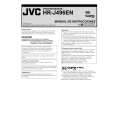
2. How to install (Centering the mounting position) When the capstan motor has once been removed and then reinstalled out of the initial correct position in the rotational direction, the capstan motor current may be unstable during operation in high or low temperatures. This may result in greater Wow & Flutter and occasionally in power breakdown because of current over - load. Install the capstan motor while following the procedure given below. (The capstan motor is centrally located when the unit is shipped from the factory.) (1) Provisionally tighten the three screws (A) securing the capstan motor. (2) Install the mechanism assembly to which the capstan motor is provisionally fastened on the bottom chassis which incorporates the Main board assembly. (No need to tighten the screws for mounting the mechanism.) Make sure that all the connectors for the mechanism assembly and the Main board assembly are correctly installed as indicated in Fig. 2-2-8b. (3) Making sure that the connector for the capstan motor is correctly mounted, and securely tighten the three screws (A). Note: � When the capstan motor has been replaced with a new one, perform recording in the EP(or LP) mode for at least 2 minutes at normal temperatures immediately be-
Motor pulley Worm gear Belt
Fig. 2-2-7a 2.2.8 Capstan Motor 1. How to remove (1) Remove the belt (capstan) on the mechanism assembly back side. (2) Remove the three screws (A) and remove the capstan motor.
Screws(A) Screw(A)
fore starting the FF/REW or SEARCH operations (Aging).
Capstan motor
2.2.9 Pole Base Assembly (supply or take-up side) 1. How to remove (1) Remove the UV catcher 2 on the removal side by loosening the screw (A). (2) Remove the pole base assembly on the supply side from the mechanism assembly by loosening the screw (B) on the mechanism assembly back side and sliding the pole base assembly toward the UV catcher 2. (3) As for the pole base assembly on the take-up side, turn the pulley of the loading motor to lower the cassette holder because the screw (B) is hidden under the control plate. (See the �Procedures for Lowering the Cassette holder assembly� of 1.3 DISASSEMBLY/ASSEMBLY METHOD.) Further turn the motor pulley to move the cassette holder until the screw (B) is no longer under the control plate (in the half-loading position). Then remove it as done for the supply side by removing the screw (B). Note: � After reinstalling the Pole base assembly and the UV catcher2, be sure to perform compatibility adjustment.
Screw(A) UV catcher2 Screw(A)
Belt
Fig. 2-2-8a
Spacer
Spacer
UV catcher2
Connector for the capstan motor
Fig. 2-2-8b
Screw(B)
Fig. 2-2-9a 2-9
|
|
|
> |
|