|
|
|
Kategorie
|
|
Informacje
|
|
Polecamy
|
|
|
 |
|
|
Dla tego produktu nie napisano jeszcze recenzji!
 ;
...instruction is ok.
...instrukcja jest ok.
Thanks/Dzięki
;
Documentation made available quickly and It is good quality. Thanks.
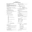
3.2.2 FM waveform linearity
Signal Mode Equipment Measuring point External trigger Adjustment part Specified value Adjustment tool (A1) (A2) (B) (C) (D) (E) (F) (G) (H)
� Proper waveform variation
� Alignment tape(SP, stairstep, NTSC) [MHP] � Alignment tape(EP, stairstep, NTSC) [MHP-L] � PB � Oscilloscope � TP106 (PB. FM) � TP111 (D.FF) � Guide roller [Mechanism assembly] � Flat V.PB FM waveform � Roller driver [PTU94002]
� Improper waveform variation Up
Down
A
B
(1) Play back the alignment tape (A1). (2) Apply the external trigger signal to D.FF (E), to observe the V.PB FM waveform at the measuring point (D). (3) Set the VCR to the manual tracking mode. (4) Make sure that there is no significant level drop of the V.PB FM waveform caused by the tracking operation, with its generally parallel and linear variation ensured. Perform the following adjustments when required. (See Fig. 3-2-2b.) (5) Reduce the V.PB FM waveform by the tracking operation. If a drop in level is found on the left side, turn the guide roller of the pole base assembly (supply side) with the roller driver to make the V.PB FM waveform linear. If a drop in level is on the right side, likewise turn the guide roller of the pole base assembly (take-up side) with the roller driver to make it linear. (See Fig. 3-2-2b.) (6) Make sure that the V.PB FM waveform varies in parallel and linearly with the tracking operation again. When required, perform fine-adjustment of the guide roller of the pole base assembly (supply or take-up side). (7) Unload the cassette tape once, play back the alignment tape (A1) again and confirm the V.PB FM waveform. (8) After adjustment, confirm that the tape wrinkling does not occur at the roller upper or lower limits. (See Fig. 3-2-2a.) [Perform adjustment step (9) only for the models equipped with SP mode and EP (or LP) mode.] (9) Repeat steps (1) to (8) by using the alignment tape (A2).
Roller driver
C
D
Guide roller (supply side)
Fig. 3-2-2b 3.2.3 Height and tilt of the A/C head Note: � Set a temporary level of the height of the A/C head in advance to make the adjustment easier after the A/C head has been replaced. (See �section 2 mechanism�.)
Signal Mode Equipment Measuring point External trigger (A) (B) (C) (D1) (D2) (E) (F) (G)
� Alignment tape(SP, stairstep, NTSC) [MHP] � PB � Oscilloscope � AUDIO OUT terminal � TP4001 (CTL. P) � TP111 (D.FF) � A/C head [Mechanism assembly] � Maximum waveform
Improper
Proper
Adjustment part Specified value
(a) GUIDE ROLLER
(b) GUIDE POLE
Fig. 3-2-2a
(1) Play back the alignment tape (A). (2) Apply the external trigger signal to D.FF (E), to observe the AUDIO OUT waveform and Control pulse waveform at the measuring points (D1) and (D2) in the ALT mode. (3) Set the VCR to the manual tracking mode. (4) Adjust the AUDIO OUT waveform and Control pulse waveform by turning the screws (1), (2) and (3) little by little until both waveforms reach maximum. The screw (1) and (3) are for adjustment of tilt and the screw (2) for azimuth.
Head base
(2) (1) AUDIO OUT
A/C head
CTL. P (3)
Fig. 3-2-3a
3-3
 $4.99 HR-S5901U JVC
Schematy Zestaw schematów dla tego urządzenia. Plik PDF zawierający schematy będzie dostarczony na Twó…
|
|
|
> |
|