|
|
|
Kategorie
|
|
Informacje
|
|
Polecamy
|
|
|
 |
|
|
Dla tego produktu nie napisano jeszcze recenzji!
 ;
Wszystko w porządku.
Instrukcja czytelna i kompletna.
Dziękuję.
all right!
thank you.
;
Bardzo dobra instrukcja. Zawiera wszystko co potrzeba, polecam!
 ;
Instrukcja jest OK. Schematy czytelne, opisane niektóre procedury.
;
Instrukcja bardzo czytelna. zawiera co potrzeba. Polecam
;
...instrukcja serwisowa w pełni czytelna i kompletna. Dziękuję!
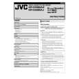
2.2.17 Take-up lever, take-up head and control plate guide (1) Remove the spring of the take-up lever from the main deck. (2) Remove the lug (A) of the take-up lever from the main deck and pull out the take-up lever and the take-up head together. (3) Remove the screw (A). (4) Align the idler arm assembly pin in the center (centre) of the R section of the control plate guide, remove the control plate guide lugs (B) and (C) from the main deck, and remove the control plate guide.
Idler arm assembly pin Lug(C) Take-up lever
Spring Sub brake Lug(A) assembly (take-up side)
Lug(B)
Lug(C)
Fig. 2-2-19a 2.2.20 Main brake assembly (take-up side), reel disk (take-up side) and main brake assembly (supply side) 1. How to remove (1) Move the main brake assembly (take-up side) in the arrow-indicated direction and remove the reel disk (takeup side). (2) Remove the spring attached to the main brake assembly. (3) Remove the lug (A) of the main brake assembly (takeup side) and pull out the lug (B) after bringing it into alignment with the main deck notch. (4) Remove the lugs (C), (D) and (E) of the main brake assembly (supply side) from the main deck and pull them off. (See Fig.2-2-20a.) (5) When installing the main brake assembly (take-up side), slide the brake lever in the direction as indicated by the arrow to prevent it from hitting the projection of the main brake assembly (take-up side). (See Fig.2-2-20b.)
Main brake assembly (supply side) Reel disk (take-up side) Main brake assembly (take-up side)
Screw(A) Take-up head
Lug(A) Lug(B)
Control plate guide
Fig. 2-2-17a 2.2.18 Capstan brake assembly
1. How to remove (1) Move the lug (A) of the capstan brake assembly in the arrow-indicated direction so that it comes into alignment with the notch of the main deck. (See Fig. 2-2-18a.) (2) Remove the lug (B) of the capstan brake assembly from the main deck and remove the capstan brake assembly.
Lug(B)
Lug(A)
Lug(B) Notch Lug(C) Lug(D) Lug(E) Spring Lug(A)
Capstan brake assembly
Fig. 2-2-20a Fig. 2-2-18a
Rotary encoder guide ( 1) Brake lever Projection of the main brake assembly (take-up side)
2.2.19 Sub brake assembly (take-up side) 1. How to remove (1) Remove the spring attached to the lid guide and sub brake assembly (take-up side). (2) Bring the lug (A) of the sub brake assembly (take-up side) into alignment with the notch of the main deck. (3) Remove the lugs (B) and (C) of the sub brake assembly (take-up side) from the main deck and remove the sub brake assembly (take-up side).
*
Note: � The parts with marked ( ) have different types of mechanisms (standard type or high-speed FF/REW type). 1 : Uses the standard type mechanism only.
*
*
Fig. 2-2-20b 2-13
|
|
|
> |
|