|
|
|
Kategorie
|
|
Informacje
|
|
Polecamy
|
|
|
 |
|
|
Dla tego produktu nie napisano jeszcze recenzji!
 ;
Schematy są ale można wysilić się i zrobić kolorowy skan i o większej rozdzielczości. Wtedy schematy płytek będą czytelniejsze. Całość super jako wartość merytoryczna. Wszystkie dane potrzebne do podłączenia różnego rodzajów urządzeń takich gramofon, CD itd.
 ;
Szybko, sprawnie i tanio. Serwis godny polecenia. Będę polecał innym
;
Ogólnie jest OK, z wyjątkiem obrazu płyty głównej, który jest miejscami mało czytelny, ale można sobie poradzić.
;
Dokładna dokumentacja, pomogła w szybkiej naprawie telewizora. Dziękuję!
;
jedyne do czego mogę mieć zastrzeżenie to jakość zdjęć zawartych w przesłanej instrukcji serwisowej ponieważ są fatalnej jakości, praktycznie nieczytelne. tak poza tym jestem zadowolony to jest to czego szukałem.
5
6
7
8
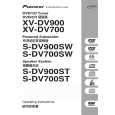
3 FAN detection circuit
5 IC81 abnormal temperature detection circuit
VD+5 VPF+15 IC81 NJM7805FA TH111 NCP18WF104J03RB to XPROTECT
C
6CH AMP
VD+5
C
6CH AMP
A
to XPROTECT (µ-com)
R108 27k
C2 B2 E C
R3654 1.8k D3658 UDZS7.5B
B
A A
Q3652 DTA124TK R3657 33(1/4W) FAN+ D3655 1SS133 FAN� D3651-D3654 1SS133�4 R3656 22k V-12F R111 1k
R113 220
Q111 2SC4081
Q3651_2/2 RN1901
E2
+
R3658 2.2k
R112 1k
Q3651_1/2 C3652 D3657 RN1901 47/50 1SS355 R3655 8.2k Q3654 2SD2144S
The voltage at Point A becomes the divided voltage of TH111 and R111//R112 (combined resistance of parallel-connected resistors R111 and R112.) In Normal mode, the resistance at TH111 is much higher than R111//R112, and Q111 is off. (Note that the resistance at TH111 becomes lower as the temperature increases.) If the solder temperature at IC81 increases abnormally, the temperature at TH111 (thermistor) mounted closest to the land of IC81 increases accordingly, and the resistance at TH111 decreases. When the temperature at TH111 reaches 90-110_C (varying according to conditions,) the voltage at Point (A) becomes high enough to turn Q111 on, and the level of the XPROTECT line becomes low. The microcomputer detects the XPROTECT level and shuts the power to the unit off.
B
If no fan is connected between FAN+ and FAN-, or when the fan cannot rotate because of a foreign object caught in the blades, current will not flow to R3657, and Q3652 and Q3651-1/2 (E, C, B) are turned off. Then Q3651-2/2 (E2, B2, C2) is turned on, and the level of XPROTECT becomes low. � The microcomputer detects the XPROTECT level and shuts the power to the unit off. When FAN+ and FAN- are short-circuited, the electric potential at Point A becomes higher than GND level by the addition of the values at D3656 and D3657. As this value is lower than that at D3658, Q3651 (E, C, B) is turned off, Q3651 (E2, B2, C2) is turned on, and the level of XPROTECT becomes low.
C
4 DC detection circuit of SP terminal
D
POWER Assy
C
VD+5
6CH AMP
+5V R3357 (R3457) 18k Q3605 R3358 (R3458) 18k + R3603 10k C3602 100/10 Q3604 Q3607 Q3606
E B C
R108 27k
D
XPROTECT
Front L ch (SW, SL) Front R ch (C, SR)
� In Normal mode, both Q3605 and Q3604 are off. (1) When positive (+) DC voltage is generated at the SP terminal When positive (+) DC voltage is generated at the L or R channel, and VB of Q3605 becomes higher than that at the operation point, Q3606 (E, C, B) is turned on, and the level of XPROTECT becomes low. � The microcomputer detects the XPROTECT level and shuts the power to the unit off. (2) When negative (-) DC voltage was generated at the SP terminal Q3604 is turned on, and XPROTECT is activated.
E
F
S-DV900SW
5 6 7 8
39
|
|
|
> |
|