|
Dla tego produktu nie napisano jeszcze recenzji!
 ;
Wszystko w porządku.
Instrukcja czytelna i kompletna.
Dziękuję.
all right!
thank you.
;
Bardzo dobra instrukcja. Zawiera wszystko co potrzeba, polecam!
 ;
Instrukcja jest OK. Schematy czytelne, opisane niektóre procedury.
;
Instrukcja bardzo czytelna. zawiera co potrzeba. Polecam
;
...instrukcja serwisowa w pełni czytelna i kompletna. Dziękuję!
4. PRECAUTIONS
To prevent damage of the thermal head caused by static electricity when assembling the chassis ass'y into the unit, the following steps must be followed; 1. Turn the power switch off. 2. Discharge the capacitor C15 (2200µF) on the PCB Z554-1. 3. Connect the FPC of chassis ass'y into a connector CN201 of the Z554-2 ass'y. 4. Assemble the chassis ass'y. 5. Turn the power switch on. (Refer to the Disassembly view (Z554-1 ass'y) of 17 page.))
Figure-2
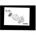
5. MEASUREMENT
Measure each value according to the following table and figure, if necessary. Measurement point Vcc Vp Ibat+ (Displaying) Ibat+ (Printing) Ibat+ (Power off) Min. Max. Min. Max. Typ. Max. Typ. Max. Typ. Max. Voltage/Current 4.875 V 5.125 V 10.78 V 11.22 V 9 mA 19 mA 0.6 A 0.7 A 10 µA 30 µA When printing at diagnostic program PRINT CHECK 2 Turning power switch off. Turning power switch on. Ip = 300 mA Icc = 30 mA Condition
Note: Ibat+ = Power source (Batteries) Vbat+ = 11 V ± 2% Table-2
Figure-3
�3�
|