|
Dla tego produktu nie napisano jeszcze recenzji!
 ;
Wszystko w porządku.
Instrukcja czytelna i kompletna.
Dziękuję.
all right!
thank you.
;
Bardzo dobra instrukcja. Zawiera wszystko co potrzeba, polecam!
 ;
Instrukcja jest OK. Schematy czytelne, opisane niektóre procedury.
;
Instrukcja bardzo czytelna. zawiera co potrzeba. Polecam
;
...instrukcja serwisowa w pełni czytelna i kompletna. Dziękuję!
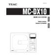
MC-DX10
2 ADJUSTMENTS AND CHECKS
2-1 TUNER SECTION
Use a screwdriver with a plastic or ceramic grip for all adjustment.
2-1-1 FM adjustment
1. Set the function switch to the FM position. 2. Connect the signal generator output through a 75 ohm dummy antenna to "ANT" on MAIN PCB. 3. Connect the oscilloscope to the speaker terminal. 4. Set the signal generator as listed in the alignment chart.
2-1-2 AM adjustment
1. Set the function switch to the AM position. 2. Connect the test loop antenna across the output of the signal generator. 3. Connect the oscilloscope to the speaker terminal. 4. Set the signal generator as listed in the alignment chart.
2-2 Adjustment and Test Points
AM ANT COIL
T502 L501
CT501
T503
CT502
L502 CT504
CT503
MC-DX10 TUNER PCB
3
|