|
|
|
Kategorie
|
|
Informacje
|
|
Polecamy
|
|
|
 |
|
|
Dla tego produktu nie napisano jeszcze recenzji!
 ;
Schematy są ale można wysilić się i zrobić kolorowy skan i o większej rozdzielczości. Wtedy schematy płytek będą czytelniejsze. Całość super jako wartość merytoryczna. Wszystkie dane potrzebne do podłączenia różnego rodzajów urządzeń takich gramofon, CD itd.
 ;
Szybko, sprawnie i tanio. Serwis godny polecenia. Będę polecał innym
;
Ogólnie jest OK, z wyjątkiem obrazu płyty głównej, który jest miejscami mało czytelny, ale można sobie poradzić.
;
Dokładna dokumentacja, pomogła w szybkiej naprawie telewizora. Dziękuję!
;
jedyne do czego mogę mieć zastrzeżenie to jakość zdjęć zawartych w przesłanej instrukcji serwisowej ponieważ są fatalnej jakości, praktycznie nieczytelne. tak poza tym jestem zadowolony to jest to czego szukałem.
MX-GT700
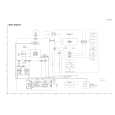
Removing the heat sink & amp. board (See Fig.8, 11 and 12)
Prior to performing the following procedure, remove the metal cover and CD changer unit. 1. Disconnect the card wire from the connector ACW1 and the harness from the connector ACW2, ACW5 and ACW6 on the amp. board. 2. Remove the four screws I attaching the heat sink cover to the rear panel. Remove the heat sink cover. 3. Remove the four screws J attaching the heat sink and two screws K attaching the speaker terminal to the rear panel. 4. After moving the heat sink upward, remove the claws. Then pull out the heat sink & amp. board inward. If the voice board is removed at this time, it will be able to work comfortably.
Heat sink cover
Joint2
(Bottom side)
H
Fig.10
Rear panel
I
I
Removing the fan motor (See Fig.8 and 12)
Prior to performing the following procedure, remove the metal cover and heat sink cover.
1. Disconnect the harness from the connector ACW5 on the amp. board. Fig.11
L J
Rear panel
2. Remove the two screws L attaching the fan motor Claws to the rear panel. Heat sink
M N K
Removing the tuner board (See Fig.12 and 13)
Prior to performing the following procedure, remove the metal cover. 1. Disconnect the card wire from the connector CON01 on the tuner board. 2. Remove the two screws M attaching the tuner board to the rear panel.
J
Speaker terminal
O P
Fig.12
Main board CON01 Rear panel
Tuner board
Removing the rear panel
(See Fig.12)
Prior to performing the following procedure, remove the metal cover, CD changer unit, heat sink & amp. board and tuner board. 1. Remove the two screws N, screw O and three screws P attaching the rear panel.
Fig.13
1-7
 $4.99 MX-GT700 JVC
Schematy Zestaw schematów dla tego urządzenia. Plik PDF zawierający schematy będzie dostarczony na Twó…
|
|
|
> |
|