|
Dla tego produktu nie napisano jeszcze recenzji!
 ;
Dokładna dokumentacja, pomogła w szybkiej naprawie telewizora. Dziękuję!
 ;
jedyne do czego mogę mieć zastrzeżenie to jakość zdjęć zawartych w przesłanej instrukcji serwisowej ponieważ są fatalnej jakości, praktycznie nieczytelne. tak poza tym jestem zadowolony to jest to czego szukałem.
;
Wszystko w porządku.
Instrukcja czytelna i kompletna.
Dziękuję.
all right!
thank you.
;
Bardzo dobra instrukcja. Zawiera wszystko co potrzeba, polecam!
;
Instrukcja jest OK. Schematy czytelne, opisane niektóre procedury.
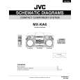
MX-KA6
Removing the power amp and supply PCB and the power trans PCB (See Fig. 2, 29 to 31)
Prior to performing the following procedures, remove the top cover and CD changer unit. 1. Remove four screws B from the rear panel. (Fig.3) 2. Pull the heat sink cover outward. 3. Remove four screws AA from the rear panel between the heat sink holder. 4. Remove two screws X that retain the speaker terminals and AUX terminal. 5. Remove screws YY that retains the rear panel, and then remove the rear panel. 6. Disconnect the parallel wires from the connectors FW951 on the power trans PCB. 7. Remove the clamp of AC power cord from the chassis. 8. Remove four screws AB that retain the power trans PCB and then remove the assembly.
Fuse (F952) T3.15A 250V Fuse (F951) T1.6A 250V
AA
X
Fuse (F953) T1.25A 250V
Fig.29
Clamp
YY
Fig.30
Rear panel
AB Power amp and supply PCB
Chassis
Fig.31
1-17
 $4.99 MX-KA6 JVC
Schematy Zestaw schematów dla tego urządzenia. Plik PDF zawierający schematy będzie dostarczony na Twó…  $4.99 MX-KA6 JVC
Katalog Części Katalog części w formie pliku PDF. Plik zawiera wykaz części znajdujących się w urządzeniu wr…
|