|
Dla tego produktu nie napisano jeszcze recenzji!
 ;
...instruction is ok.
...instrukcja jest ok.
Thanks/Dzięki
;
Documentation made available quickly and It is good quality. Thanks.
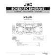
3.2.14 Removing the Power amp and supply PCB and the power trans PCB (See Fig. 3, 29 to 31) � Prior to performing the following procedures, remove the top cover and CD changer unit. (1) Remove four screws B from the rear panel. (Fig.3) (2) Pull the heat sink cover outward. Fuse(F953) (3) Remove four screws AA from the rear panel between the heat sink holder. (4) Remove four screws YY that retains the rear panel, and then remove the rear panel. (5) Disconnect the parallel wires from the connectors FW951 on the power trans PCB. (6) Remove screws Z that retain the power amp and supply PCB and then remove the assembly. (7) Remove the clamp of AC power cord from the chassis. (8) Remove four screws that retain the power trans PCB and then remove the assembly.
T1.6AL 250V
Fuse(F951) T3.15AL 250V Fuse(F952) T1.6AL 250V
Fig.29
AA
Clamp YY Fig.30 Rear panel Power amp and supply PCB
Z
Chassis Fig.31
1-18 (No.MB254)
 $4.99 MX-KB4 JVC
Schematy Zestaw schematów dla tego urządzenia. Plik PDF zawierający schematy będzie dostarczony na Twó…  $4.99 MX-KB4 JVC
Katalog Części Katalog części w formie pliku PDF. Plik zawiera wykaz części znajdujących się w urządzeniu wr…
|