|
|
|
Kategorie
|
|
Informacje
|
|
Polecamy
|
|
|
 |
|
|
Dla tego produktu nie napisano jeszcze recenzji!
 ;
jedyne do czego mogę mieć zastrzeżenie to jakość zdjęć zawartych w przesłanej instrukcji serwisowej ponieważ są fatalnej jakości, praktycznie nieczytelne. tak poza tym jestem zadowolony to jest to czego szukałem.
 ;
Wszystko w porządku.
Instrukcja czytelna i kompletna.
Dziękuję.
all right!
thank you.
;
Bardzo dobra instrukcja. Zawiera wszystko co potrzeba, polecam!
;
Instrukcja jest OK. Schematy czytelne, opisane niektóre procedury.
;
Instrukcja bardzo czytelna. zawiera co potrzeba. Polecam
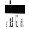
ADJUSTMENT (TUNER / DECK / FRONT)
< TUNER SECTION > <U, LH>
1. Clock Frequency Check Settings : � Test point : TP2 (CLK) Method : Set to AM 1710kHz and check that the test point is 2160kHz ± 45Hz. 2. AM VT Check Settings : � Test point : TP1 (VT) Method : Set to AM 1710kHz and check that the test point is less than 8.5V. Then set to AM 530kHz and check that the test point is more than 0.6V. 3. AM Tracking Adjustment Settings : � Test point : TP8 (Lch), TP9 (Rch) � Adjustment location : L951 (1/3) Method : Set to AM 1000kHz and adjust L951 (1/3) so that the test point becomes maximum. 4. AM IF Adjustment Settings : � Test point : TP8 (Lch), TP9 (Rch) � Adjustment location : L802 ........................... 450kHz 5. FM VT Adjustment. Settings : � Test point : TP1 (VT) � Adjustment location : L906 Method : Set to FM 108.0MHz and adjust L906 so that the test point bcomes 7.0V ± 0.1V. Then set to FM 87.5MHz and check that the test point is more than 0.4V. 6. FM Tracking Adjustment Settings : � Test point : TP8 (Lch), TP9 (Rch) � Adjustment location : L903 Method : Set to FM 87.5MHz and adjust L903 so that the test point is less than 9dBµV. 7. DC Balance / Mono Distortion Adjustment Settings : � Test point : TP3, TP4 (DC balance) TP8 (Lch), TP9 (Rch) (Mono Distortion) � Adjustment location : L801 � Input level : 60dBµV Method : Set to FM 98.0MHz and adjust L801 so that the distortion is less than 1.2%. Then check the voltage between TP3 and TP4 is 0V ± 500mV. 8. Output Level Check <AM> Settings : � Test point : TP8 (Lch), TP9 (Rch) � Input level : 74dBµV Method : Set to AM 1000kHz and check that the test point is 40mV ± 3dB. <FM> Settings : � Test point : TP8 (Lch), TP9 (Rch) � Input level : 60dBµV Method : Set to FM 98.0MHz and check that the test point is 200mV ± 3dB. 9. FM Separation Check Settings : � Test point : TP8 (Lch), TP9 (Rch) � Input level : 60dBµV Method : Set to FM 98.0MHz and check that the test point is more than 25dB.
� 32 �
|
|
|
> |
|