|
|
|
Kategorie
|
|
Informacje
|
|
Polecamy
|
|
|
 |
|
|
Dla tego produktu nie napisano jeszcze recenzji!
 ;
Bardzo dobra jakość skanu, przystępna cena. Instrukcja serwisowa okazała się przydatna przy "reanimowaniu" dwudziestoparoletniego decka, który teraz pięknie gra :)
;
...instruction is ok.
...instrukcja jest ok.
Thanks/Dzięki
;
Documentation made available quickly and It is good quality. Thanks.
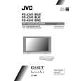
3.1.11 REMOVING THE PWB IN PDP UNIT 3.1.11.1 REMOVING THE SMPS PWB (Fig.4 )
3.1.11.6 REMOVING THE Y-BUFFER L PWB (Fig.4 )
� Remove the PDP UNIT.
(1) Disconnect the connectors [CN8002], [CN8003], [CN8004], [CN8006], [CN8007], [CN8008], [CN8009] from the SMPS PWB. (2) Remove the 8 screws [V], and remove the SMPS PWB. NOTE: � It is advisable to take note of the connecting location (connector number) of the removed connectors.
� Remove the PDP UNIT.
(1) Disconnect the connectors [CN5501], [CN5502], [CN5503], [CN5504], [CN5505],[CN5506] from the YBUFFER L PWB. (2) Remove the 5 screws [a], and remove the Y-BUFFER L PWB. NOTE: � It is advisable to take note of the connecting location (connector number) of the removed connectors.
3.1.11.2 REMOVING THE X-MAIN PWB (Fig.4 )
� Remove the PDP UNIT.
3.1.11.7 REMOVING THE E-BUFFER PWB (Fig.4 )
(1) Disconnect the connectors [CN4001], [CN4002], [CN4003], [CN4004], [CN4005] from the X-MAIN PWB. (2) Remove the 8 screws [W], and remove the X-MAIN PWB. NOTE: � It is advisable to take note of the connecting location (connector number) of the removed connectors.
� Remove the PDP UNIT.
(1) Disconnect the connectors [CN401], [CN806], [EC1], [EC2], [EC3],[EF1] from the E-BUFFER PWB. (2) Remove the 6 screws [b], and remove the E-BUFFER PWB. NOTE: � It is advisable to take note of the connecting location (connector number) of the removed connectors.
3.1.11.3 REMOVING THE Y-MAIN PWB (Fig.4 )
� Remove the PDP UNIT.
(1) Disconnect the connectors [CN5001], [CN5002], [CN5003], [CN5004], [CN5005],[CN5006], [CN5007], [CN5008] from the Y-MAIN PWB. (2) Remove the 7 screws [X], and remove the Y-MAIN PWB. NOTE: � It is advisable to take note of the connecting location (connector number) of the removed connectors.
3.1.11.8 REMOVING THE F-BUFFER PWB (Fig.4 )
� Remove the PDP UNIT.
(1) Disconnect the connectors [CN402], [FC4], [FE1], [FG1], from the F-BUFFER PWB. (2) Remove the 4 screws [c], and remove the F-BUFFER PWB. NOTE: � It is advisable to take note of the connecting location (connector number) of the removed connectors.
3.1.11.4 REMOVING THE LOGIC-MAIN PWB (Fig.4 )
� Remove the PDP UNIT.
3.1.11.9 REMOVING THE G-BUFFER PWB(Fig.4 )
(1) Disconnect the connector [CN8008] from the SMPS PWB. (2) Disconnect the connector [CN4002] from the X-MAIN PWB. (3) Disconnect the connector [CN5001] from the Y-MAIN PWB. (4) Disconnect the connector [CN401] from the E-BUFFER PWB. (5) Disconnect the connector [CN402] from the F-BUFFER PWB. (6) Disconnect the connector [CN403] from the G-BUFFER PWB. (7) Remove the 6 screws [Y], and remove the LOGIC-MAIN PWB. NOTE: � It is advisable to take note of the connecting location (connector number) of the removed connectors.
� Remove the PDP UNIT.
(1) Disconnect the connectors [CN403], [GC5], [GC6], [GC7], [GF1] from the G-BUFFER PWB. (2) Remove the 6 screws [d], and remove the G-BUFFER PWB. NOTE: � It is advisable to take note of the connecting location (connector number) of the removed connectors.
3.1.11.10 REMOVING THE VIDEO SMPS PWB (Fig.4 ) � Remove the PDP UNIT. (1) Disconnect the connectors [CN9005], [CN9006], [CN9007] from the VIDEO SMPS PWB. (2) Remove the 4 screws [e], and remove the VIDEO SMPS PWB. NOTE:
3.1.11.5 REMOVING THE Y-BUFFER U PWB (Fig. 4)
� Remove the PDP UNIT.
(1) Disconnect the connectors [CN5401], [CN5402], [CN5403], [CN5404], [CN5405],[CN5406] from the YBUFFER U PWB. (2) Remove the 5 screws [Z], and remove the Y-BUFFER U PWB. NOTE: � It is advisable to take note of the connecting location (connector number) of the removed connectors.
� It is advisable to take note of the connecting location
(connector number) of the removed connectors.
1-14 (No.YA013)
|
|
|
> |
|