|
|
|
Kategorie
|
|
Informacje
|
|
Polecamy
|
|
|
 |
|
|
Dla tego produktu nie napisano jeszcze recenzji!
 ;
Schematy są ale można wysilić się i zrobić kolorowy skan i o większej rozdzielczości. Wtedy schematy płytek będą czytelniejsze. Całość super jako wartość merytoryczna. Wszystkie dane potrzebne do podłączenia różnego rodzajów urządzeń takich gramofon, CD itd.
 ;
Szybko, sprawnie i tanio. Serwis godny polecenia. Będę polecał innym
;
Ogólnie jest OK, z wyjątkiem obrazu płyty głównej, który jest miejscami mało czytelny, ale można sobie poradzić.
;
Dokładna dokumentacja, pomogła w szybkiej naprawie telewizora. Dziękuję!
;
jedyne do czego mogę mieć zastrzeżenie to jakość zdjęć zawartych w przesłanej instrukcji serwisowej ponieważ są fatalnej jakości, praktycznie nieczytelne. tak poza tym jestem zadowolony to jest to czego szukałem.
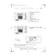
PD-F958, PD-F908
REMOVING THE SERVO MECHANISM ASSY GM
1
Turn gear pulley (B) and position Arm A2 as shown below.
6 7
Remove the connector ASSY (4P) from the float base.
Arm A2 45
Remove the float spring. (To install this part, line up the float angle side of the Servo Mechanism ASSY GM first, and press down on the float base side.)
Float Base
1 Turn
Gear Pulley(B)
7 Remove
Float Spring
Servo Stopper S
2
2 6 2
Float Angle Connector Assy(4P)
8 3 5
Slide the float base in the direction of the arrow 4 while pressing down on the loading base hook, and, lifting it gently, pull it out in the direction of the arrow 5 .
Remove the float rubber from the Servo Mechanism ASSY GM. At this time the float rubber should remain on the float base side. (To install it on the float base when it has been removed, push it into place with a thin cylindrical object.
Servo Mechanism Assy Gm
Float Rubber
5 Remove
Flloat Base
4 Move
Float Base
3
Push Hook Loading Base
45
|
|
|
> |
|