| » Pokaż Koszyk | |
 | Ilość: 1 $4.99 » Pokaż Szczegóły |
 | Ilość: 1 $4.99 » Pokaż Szczegóły |
 | Ilość: 1 $4.99 » Pokaż Szczegóły |
 | Ilość: 1 $4.99 » Pokaż Szczegóły |
 | Ilość: 1 $4.99 » Pokaż Szczegóły |
 | Ilość: 1 $4.99 » Pokaż Szczegóły |
 | Ilość: 1 $4.99 » Pokaż Szczegóły |
 | Ilość: 1 $4.99 » Pokaż Szczegóły |
 | Ilość: 1 $4.99 » Pokaż Szczegóły |
 | Ilość: 1 $4.99 » Pokaż Szczegóły |
 | Ilość: 1 $4.99 » Pokaż Szczegóły |
 | Ilość: 1 $4.99 » Pokaż Szczegóły |
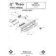 | Ilość: 1 $4.99 » Pokaż Szczegóły |
 | Ilość: 1 $4.99 » Pokaż Szczegóły |
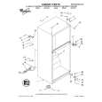 | Ilość: 1 $4.99 » Pokaż Szczegóły |
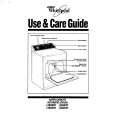 | Ilość: 1 $4.99 » Pokaż Szczegóły |
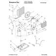 | Ilość: 1 $4.99 » Pokaż Szczegóły |
 | Ilość: 1 $4.99 » Pokaż Szczegóły |
| W sumie: $89.82 | |


