|
|
|
Kategorie
|
|
Informacje
|
|
Polecamy
|
|
|
 |
|
|
Dla tego produktu nie napisano jeszcze recenzji!
 ;
Szybko, sprawnie i tanio. Serwis godny polecenia. Będę polecał innym
 ;
Ogólnie jest OK, z wyjątkiem obrazu płyty głównej, który jest miejscami mało czytelny, ale można sobie poradzić.
 ;
Dokładna dokumentacja, pomogła w szybkiej naprawie telewizora. Dziękuję!
 ;
jedyne do czego mogę mieć zastrzeżenie to jakość zdjęć zawartych w przesłanej instrukcji serwisowej ponieważ są fatalnej jakości, praktycznie nieczytelne. tak poza tym jestem zadowolony to jest to czego szukałem.
 ;
Wszystko w porządku.
Instrukcja czytelna i kompletna.
Dziękuję.
all right!
thank you.
Programmable power supplies
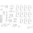
(Processor schematic page 3) Various voltages required by different types of EPROMs are generated by two programmable power supplies. Half of U36, Q1, Q3, Q4, and Q6 are the active components in the VPP supply. VPP has a range of zero to +27 volts, the output controlled by the reference voltage VPPREF which is produced by a digitally programmed DAC/sample/hold circuit. The supply circuit is current limited and has a voltage gain which is determined by R93 and R94. Digital signal VPPSEL* must be at logic zero to enable the VPP supply. The other half of U36, Q2 and Q5 make up the VCC programmable supply which has an output range of zero to +8 volts. The gain of the VCC circuit is determined by R97 and R99. VCC is also current limited and the circuit is enabled by a logic zero on VCCSEL*.
Battery backup
(Processor schematic page 3) In order to retain the contents of memory at all times, a three volt lithium battery supplies power to the CMOS RAM through R141 and D26 when the main power is off. When the power is on, the +5v supply powers the RAM through D25.
RESET circuitry
(Processor schematic page 5) The PUP (Power UP) circuitry consisting of active components Q10 and U65 disables writing to RAM when power is off. PUP is connected to all 6264 ICs directly and to the 6116 RAM through U41. PUP is also buffered by U41 to provide a RESET* signal for the microprocessor and certain latches. The PUP circuit is very sensitive to sudden changes in the +5 volt power supply. If the ripple on the +5 line is too great, PUP will trigger and RESET* will go low, resetting the microprocessor.
Microprocessor and memory
(Processor schematic page 1) The 68B09 microprocessor chip (U38) along with the firmware contained in EPROMs U51 and U52 control all operations of the Prommer. The main
Prommer Service Manual
8
 $4.99 PROMMER OBERHEIM
Schematy Zestaw schematów dla tego urządzenia. Plik PDF zawierający schematy będzie dostarczony na Twó…
|
|
 |
> |
|
