|
Dla tego produktu nie napisano jeszcze recenzji!
 ;
Schematy są ale można wysilić się i zrobić kolorowy skan i o większej rozdzielczości. Wtedy schematy płytek będą czytelniejsze. Całość super jako wartość merytoryczna. Wszystkie dane potrzebne do podłączenia różnego rodzajów urządzeń takich gramofon, CD itd.
 ;
Szybko, sprawnie i tanio. Serwis godny polecenia. Będę polecał innym
;
Ogólnie jest OK, z wyjątkiem obrazu płyty głównej, który jest miejscami mało czytelny, ale można sobie poradzić.
;
Dokładna dokumentacja, pomogła w szybkiej naprawie telewizora. Dziękuję!
;
jedyne do czego mogę mieć zastrzeżenie to jakość zdjęć zawartych w przesłanej instrukcji serwisowej ponieważ są fatalnej jakości, praktycznie nieczytelne. tak poza tym jestem zadowolony to jest to czego szukałem.
5
6
7
8
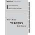
Note) This product has high voltage circuits inside, and the voltage will be kept for a while by big capacitors. So, before starting disassembly(especially removing the Buss Bars(CND3947)), make sure if the voltage of +VH and -VH become low enough after turning off the power supply(+B & ACC). If you want to discharge the capacitors faster, connect the resistors of same value in parallel with the original discharge resistors (R241 - R246).
A
- Removing the Amp Unit (Fig.3)
1
Remove the eight screws and then remove the four Buss Bars.
2 3 4 5
Remove the two screws. Remove the four screws.
B
Remove the seven screws.
Disconnect the Connector and then remove the Amp Unit.
C
Note) Removal of substrate while the Buss Bar being connected will deform the Buss Bar, failing to set up again. Buss Bar
1
1 5
1 1
1
3
1 4
1 4 4
1
3
3
4 4 4 4
D
3 2
2
Amp Unit
Fig.3 Note) Remove a screw for MODE SELECT only when switching over the mode selection.You do not have to remove this screw when removing the unit board. (Fig.4)
E
Screw for MODE SELECT Fig.4
F
PRS-D2000SPL/XU/UC
5 6 7 8
15
|