|
|
|
Kategorie
|
|
Informacje
|
|
Polecamy
|
|
|
 |
|
|
Dla tego produktu nie napisano jeszcze recenzji!
 ;
Szybko, sprawnie i tanio. Serwis godny polecenia. Będę polecał innym
 ;
Ogólnie jest OK, z wyjątkiem obrazu płyty głównej, który jest miejscami mało czytelny, ale można sobie poradzić.
;
Dokładna dokumentacja, pomogła w szybkiej naprawie telewizora. Dziękuję!
;
jedyne do czego mogę mieć zastrzeżenie to jakość zdjęć zawartych w przesłanej instrukcji serwisowej ponieważ są fatalnej jakości, praktycznie nieczytelne. tak poza tym jestem zadowolony to jest to czego szukałem.
;
Wszystko w porządku.
Instrukcja czytelna i kompletna.
Dziękuję.
all right!
thank you.
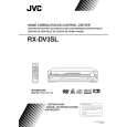
RX-DV3SL
Disassembly method
Removing the top cover (See Fig.1)
1. Remove the four screws marked A attaching the top cover on both sides of the body. 2. Remove the three screws marked B on the back of the body. 3. Remove the top cover from behind in the direction of
Top cover
B
A
2
A
2
Fig.1
Front panel assembly
Removing the front panel assembly (See Fig.2 to 4)
Prior to performing the following procedures, remove the top cover. 1. Disconnect the card wire from the connector CN114 on the main board. 2. Remove the five screws marked C attaching the front panel assembly on the bottom of the body. Detach the front panel assembly toward the front. 3. Release the two joints marked a on both sides on the bottom of the body using a screwdriver.
Tie band Power supply board
CN114 Main board Amplifier board
CN201 DSP board
Power /Fuse board
Fig.2
Front panel assembly
C
C
Joint a
Fig.4 Fig.3
Removing the rear panel
(See Fig.5)
Cord stopper Rear panel
Prior to performing the following procedures, remove the top cover. 1. Remove the power cord stopper from the rear panel by moving it in the direction of the arrow. 2. Remove the twenty one screws marked D attaching each boards to the rear panel on the back of the body. 3. Remove the three screws marked E attaching the rear panel on the back of the body.
D
D
E
DE
Fig.5
D
E
1-5
|
|
|
> |
|