|
Dla tego produktu nie napisano jeszcze recenzji!
 ;
jedyne do czego mogę mieć zastrzeżenie to jakość zdjęć zawartych w przesłanej instrukcji serwisowej ponieważ są fatalnej jakości, praktycznie nieczytelne. tak poza tym jestem zadowolony to jest to czego szukałem.
 ;
Wszystko w porządku.
Instrukcja czytelna i kompletna.
Dziękuję.
all right!
thank you.
;
Bardzo dobra instrukcja. Zawiera wszystko co potrzeba, polecam!
;
Instrukcja jest OK. Schematy czytelne, opisane niektóre procedury.
;
Instrukcja bardzo czytelna. zawiera co potrzeba. Polecam
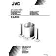
SX-DD3
Disassembly method
Removing the amplifier assembly (See Fig. 1~3)
1. Remove the eleven screws A attaching the amplifier assembly. 2. Pull out the amplifier assembly. 3. Remove the felt sheet from vibration prevention of the wire connector in the reverse side of the amplifier assembly. 4. Remove the connection of 3 wire connectors in the reverse side of the amplifier assembly.
Cabinet
A
A
A
Rear panel Fig. 1
Note: Before attaching the amplifier assembly the felt sheet is wound to the wire connector for the vibration prevention of the wire connector. Attaching the tie band from the top of the felt sheet.
A
Tie band
Removing the rear panel
Remove the amplifier assembly. 1. Remove the volume knob.
(See Fig. 4)
Felt sheet
2. Remove the three screws B attaching the rear panel .
Amp. assay
Vol. knob
Cabinet
Amp.
B
Cord connecter
Felt sheet
Fig. 4
Rear panel
Fig. 3
1-3
|