|
|
|
Kategorie
|
|
Informacje
|
|
Polecamy
|
|
|
 |
|
|
Dla tego produktu nie napisano jeszcze recenzji!
 ;
Dokładna dokumentacja, pomogła w szybkiej naprawie telewizora. Dziękuję!
 ;
jedyne do czego mogę mieć zastrzeżenie to jakość zdjęć zawartych w przesłanej instrukcji serwisowej ponieważ są fatalnej jakości, praktycznie nieczytelne. tak poza tym jestem zadowolony to jest to czego szukałem.
;
Wszystko w porządku.
Instrukcja czytelna i kompletna.
Dziękuję.
all right!
thank you.
;
Bardzo dobra instrukcja. Zawiera wszystko co potrzeba, polecam!
;
Instrukcja jest OK. Schematy czytelne, opisane niektóre procedury.
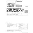
SECTION 3 ELECTRICAL ADJUSTMENT
BIAS ADJUSTMENT
Adjustment Procedure: 1. Rotate fully the bias adjusting semi-fixed resistors (RV301 (LCH), RV351 (R-CH)) to the minimum position (counterclockwise). 2. Connect a digital voltmeter to the CN406 (L-CH) and CN407 (R-CH).
pin 1 pin 3 CN406 (L-CH) CN407 (R-CH) � + + �
Connection and Adjustment Location:
[MAIN (A) BOARD] � Component side �
3. Set the slidack to 0 V AC, and press the POWER button (ON) on the set. 4. Raise gradually the slidack voltage up to the rated voltage (230 V AC). 5. At this time, confirm that the speaker relay is turned on (it will click). 6. Adjust the RV301 (L-CH) and RV351 (R-CH) so that a reading of digital voltmeter is from 10 mV to 20 mV. 7. Return the slidack to 0 V AC, and press the POWER button (OFF) on the set.
C372 C322
RV351 (R-CH) BIAS Adjustment
RV301 (L-CH)
[MAIN (B) BOARD] � Component side �
CN407 3 1
digital voltmeter C459
+ �
C409
1
3
CN406
�7�
|
|
|
> |
|