|
|
|
Kategorie
|
|
Informacje
|
|
Polecamy
|
|
|
 |
|
|
Dla tego produktu nie napisano jeszcze recenzji!
 ;
Dokładna dokumentacja, pomogła w szybkiej naprawie telewizora. Dziękuję!
 ;
jedyne do czego mogę mieć zastrzeżenie to jakość zdjęć zawartych w przesłanej instrukcji serwisowej ponieważ są fatalnej jakości, praktycznie nieczytelne. tak poza tym jestem zadowolony to jest to czego szukałem.
;
Wszystko w porządku.
Instrukcja czytelna i kompletna.
Dziękuję.
all right!
thank you.
;
Bardzo dobra instrukcja. Zawiera wszystko co potrzeba, polecam!
;
Instrukcja jest OK. Schematy czytelne, opisane niektóre procedury.
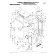
7.22. Remove (Squawker)
the
Speaker
7.24. Remove the K-Board and SBoard
1. Remove the Cabinet assy. (See section 7.21.) 2. Remove the Speaker (Squawker /L). (See section 7.22.) 3. Remove the screws (�3 ,�1 ) and remove the Bottom shield L and the S-Board shield plate.
1. Remove the Cabinet assy. (See section 7.21.) 2. Disconnect the relay connectors. 3. Remove the screws (�2 each). 4. Remove the Speaker (Squawker/L, Squawker/R).
7.23. Remove the GL-Board
1. Remove the Cabinet assy. (See section 7.21.) 2. Remove the Speaker (Squawker /R). (See section 7.22.) 3. Remove the screws (�3 shield R. ) and remove the Bottom
4. Remove the screws (�2 ). 5. Disconnect the connector (K1) and remove the K-Board.
6. Remove the screws (�2 unit. 4. Disconnect the connector (GL02). 5. Remove the screws (�2 ) and remove the GL-Board.
) and remove the S-Board
7. Disconnect the connector (S2). 8. Remove the screws (�1 ) and remove the S-Board.
24
|
|
|
> |
|