|
|
|
Kategorie
|
|
Informacje
|
|
Polecamy
|
|
|
 |
|
|
Dla tego produktu nie napisano jeszcze recenzji!
 ;
jedyne do czego mogę mieć zastrzeżenie to jakość zdjęć zawartych w przesłanej instrukcji serwisowej ponieważ są fatalnej jakości, praktycznie nieczytelne. tak poza tym jestem zadowolony to jest to czego szukałem.
 ;
Wszystko w porządku.
Instrukcja czytelna i kompletna.
Dziękuję.
all right!
thank you.
;
Bardzo dobra instrukcja. Zawiera wszystko co potrzeba, polecam!
;
Instrukcja jest OK. Schematy czytelne, opisane niektóre procedury.
;
Instrukcja bardzo czytelna. zawiera co potrzeba. Polecam
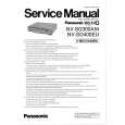
3. Main PCB Removal.
1) Remove the connector !0 (N901) of the degauss coil. 2) Remove the DY connector !1 and !2. 3) Remove the anode cap. 4) Remove two ground connector !3. 5) Move the CRT face down and remove two screws !4 securing the bottom fitting metal. 6) Remove the fitting metal and the PCB from the cabinet. 7) Remove five screws !5 securing the fitting metal and PCB. 8) Remove the PCB !6 with the figure referenced.
!5 !5
!5 !6
!4 !3 !3
!4
!1 !2
!0 N901
WARNING
The following label is stuck to the CRT GND Cable: In particular, when energizing the MAIN PCB by taking it fr om the Bottom Cabnet, it is necessar y to connect the GND Cable, without fail, to the ear th terminal of AC INLET for the prevention of electric shocks.
WARNING
When removing this CRT GND cable, Connect it to GND terminal of the AC inlet to prevent electric shock.
� 15 �
|
|
|
> |
|