|
|
|
Kategorie
|
|
Informacje
|
|
Polecamy
|
|
|
 |
|
|
Dla tego produktu nie napisano jeszcze recenzji!
 ;
Dokładna dokumentacja, pomogła w szybkiej naprawie telewizora. Dziękuję!
 ;
jedyne do czego mogę mieć zastrzeżenie to jakość zdjęć zawartych w przesłanej instrukcji serwisowej ponieważ są fatalnej jakości, praktycznie nieczytelne. tak poza tym jestem zadowolony to jest to czego szukałem.
 ;
Wszystko w porządku.
Instrukcja czytelna i kompletna.
Dziękuję.
all right!
thank you.
 ;
Bardzo dobra instrukcja. Zawiera wszystko co potrzeba, polecam!
 ;
Instrukcja jest OK. Schematy czytelne, opisane niektóre procedury.
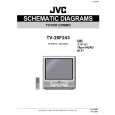
TV-20F243
ELECTRICAL ADJUSTMENTS
2-3: RF AGC 1. Receive the VHF HIGH (63dB). 2. Connect the digital voltmeter between the pin 5 of CP602 and the pin 1 (GND) of CP602. 3. Activate the adjustment mode display of Fig. 1-1 and press the channel button (02) on the remote control to select �RF AGC�. 4. Press the VOL. UP/DOWN button on the remote control until the digital voltmeter is 2.5 ± 0.05V. 2-8: HORIZONTAL PHASE 1. Receive the monoscope pattern. 2. Using the remote control, set the brightness and contrast to normal position. 3. Activate the adjustment mode display of Fig. 1-1 and press the channel button (05) on the remote control to select �H PHASE�. 4. Press the VOL. UP/DOWN button on the remote control until the SHIFT quantity of the OVER SCAN on right and left becomes minimum. 2-9: HORIZONTAL SIZE 1. Receive the monoscope pattern. 2. Adjust the VR401 until the SHIFT quantity of the OVER SCAN on right and left becomes 10 ± 2%. 2-10: VERTICAL SHIFT 1. Receive the monoscope pattern. 2. Using the remote control, set the brightness and contrast to normal position. 3. Activate the adjustment mode display of Fig. 1-1 and press the channel button (07) on the remote control to select �V SHIFT�. 4. Check if the step No. of V SHIFT is �0�. 5. Please the VOL. UP/DOWN button on the remote control until the horizontal line becomes fit to the notch of the shadow mask. 2-11: VERTICAL SIZE 1. Receive the monoscope pattern. 2. Using the remote control, set the brightness and contrast to normal position. 3. Activate the adjustment mode display of Fig. 1-1 and press the channel button (06) on the remote control to select �V SIZE�. 4. Press the VOL. UP/DOWN button on the remote control until the rectangle on the center of the screen becomes square. 5. Receive a broadcast and check if the picture is normal. 2-12: SUB BRIGHTNESS 1. Receive the monoscope pattern. (RF Input) 2. Using the remote control, set the brightness and contrast to normal position. 3. Activate the adjustment mode display of Fig. 1-1 and press the channel button (13) on the remote control to select �BRIGHTNESS�. 4. Press the VOL. UP/DOWN button on the remote control until the white 10% is starting to be visible. 5. Receive the monoscope pattern. (Audio Video Input) 6. Press the INPUT button on the remote control to set to the AV mode. Then perform the above adjustments 2~4.
(TV SECTION)
2-4: CONSTANT VOLTAGE 1. Connect the digital voltmeter to the TP501 (R502). 2. Set condition is AV MODE without signal. 3. Adjust the VR502 until the DC voltage is 115 ± 0.5V. 2-5: CUT OFF 1. Adjust the unit to the following settings. R CUT OFF=128, G CUT OFF=128, B CUT OFF=128, R DRIVE=64, B DRIVE=64, BRIGHTNESS=100, CONTRAST=85 2. Place the set with Aging Test for more than 15 minutes. 3. Set condition is AV MODE without signal. 4. Activate the adjustment mode display of Fig. 1-1 and press the channel button (01) on the remote control to select �CUT OFF�. 5. Adjust the Screen Volume until a dim raster is obtained. 2-6: WHITE BALANCE NOTE: Adjust after performing CUT OFF adjustment. 1. Place the set with Aging Test for more than 15 minutes. 2. Receive the gray scale pattern from the Pattern Generator. 3. Using the remote control, set the brightness and contrast to normal position. 4. Activate the adjustment mode display of Fig. 1-1 and press the channel button (10) on the remote control to select �R CUT OFF�. 5. Press the CH. UP/DOWN button on the remote control to select the �R CUT OFF�, �G CUT OFF�, �B CUT OFF�, �R DRIVE� or �B DRIVE�. 6. Adjust the VOL. UP/DOWN button on the remote control to whiten the R CUT OFF, G CUT OFF, B CUT OFF, R DRIVE, and B DRIVE at each step tone sections equally. 7. Perform the above adjustments 5 and 6 until the white color is looked like a white. 2-7: FOCUS 1. Receive the monoscope pattern. 2. Turn the Focus Volume fully counterclockwise once. 3. Adjust the Focus Volume until picture is distinct.
28
No. 51987
 $4.99 TV-20F243 JVC
Schematy Zestaw schematów dla tego urządzenia. Plik PDF zawierający schematy będzie dostarczony na Twó…
|
|
 |
> |
|
