|
|
|
Kategorie
|
|
Informacje
|
|
Polecamy
|
|
|
 |
|
|
Dla tego produktu nie napisano jeszcze recenzji!
 ;
Dokładna dokumentacja, pomogła w szybkiej naprawie telewizora. Dziękuję!
 ;
jedyne do czego mogę mieć zastrzeżenie to jakość zdjęć zawartych w przesłanej instrukcji serwisowej ponieważ są fatalnej jakości, praktycznie nieczytelne. tak poza tym jestem zadowolony to jest to czego szukałem.
;
Wszystko w porządku.
Instrukcja czytelna i kompletna.
Dziękuję.
all right!
thank you.
;
Bardzo dobra instrukcja. Zawiera wszystko co potrzeba, polecam!
;
Instrukcja jest OK. Schematy czytelne, opisane niektóre procedury.
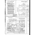
BLOCK DIAGRAM
1 A/V Jack Chroma Circuit Volume Control 4 IC400 Tuning Voltage Generator Common Driver IC300 2 VR600 Audio Amp. IC600 Speaker
LCD
3
IC700 OSC Display Control A/D Converter Auto-tuning Control
Segment Driver
VR800
5
Q800~Q801 Display Voltage Generator
Power Supply
VCC2 (4.0V) VCC6 (28 ~ 40V) VCC7 (48 ~ 72V) VEE1 (-8.4 ~ -5.6V)
Brightness Control
1 2 3
� Chroma Circuit IC300 M51286FP Generates the tricolor of red, green and blue from the video signal. � Audio Amp. IC600 TA7368F Sound amplification � OSC, A/D Converter, Display / Auto-tuning Control : IC700 MSM6525B02 GSK-64D Converts the color signal into digital signal. Also generates the clock pulse for the display, and controls the display. � Tuning Voltage Generator IC400 MSC1169MS-K Generates the tuning voltage from the tuning pulse (TU) output of 6. � Display Voltage Generator Q800 ~ 801 2SD1149, 2SD601A-Rxz Generates the display voltages V0 ~ V4 from VEE1 and VCC7 outputs of the power supply.
4 5
�2�
|
|
|
> |
|