- GENERAL
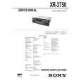
- Location of Controls (XR - 3750)
- Location of Controls (XR - C350)
- Installation
- Connections
- DISASSEMBLY
- ASSEMBLY OF MECHANISM DECK
- MECHANICAL ADJUSTMENTS
- ELECTRICAL ADJUSTMENTS
- Test Mode
- Tape Deck Section
- Tuner Section
- DIAGRAMS
- IC Pin Function Description
- Printed Wiring Boards - Main Section
- Schematic Diagram - Main Section
- Printed Wiring Board - Key Section
- Schematic Diagram - Key Section
- EXPLODED VIEWS
- ELECTRICAL PARTS LIST
Dla tego produktu nie napisano jeszcze recenzji!
 ;
Dokładna dokumentacja, pomogła w szybkiej naprawie telewizora. Dziękuję!
 ;
jedyne do czego mogę mieć zastrzeżenie to jakość zdjęć zawartych w przesłanej instrukcji serwisowej ponieważ są fatalnej jakości, praktycznie nieczytelne. tak poza tym jestem zadowolony to jest to czego szukałem.
;
Wszystko w porządku.
Instrukcja czytelna i kompletna.
Dziękuję.
all right!
thank you.
;
Bardzo dobra instrukcja. Zawiera wszystko co potrzeba, polecam!
;
Instrukcja jest OK. Schematy czytelne, opisane niektóre procedury.
SECTION 3 ASSEMBLY OF MECHANISM DECK
Note: Follow the assembly procedure in the numerical order given.
ALIGNMENT OF FRONT SWITCH
hole
1 Align ¢ mark on the rotary switch the position shown in the figure.
chassis (S) ass�y
2 Align hole in the gear (LDG-D) with the position shown in the figure.
GEAR (LDGE)
1 Align hole as shown in the figure. 2 Install the gear (LDG-E).
� 12 �
|