|
|
|
Kategorie
|
|
Informacje
|
|
Polecamy
|
|
|
 |
|
|
Dla tego produktu nie napisano jeszcze recenzji!
 ;
Dokładna dokumentacja, pomogła w szybkiej naprawie telewizora. Dziękuję!
 ;
jedyne do czego mogę mieć zastrzeżenie to jakość zdjęć zawartych w przesłanej instrukcji serwisowej ponieważ są fatalnej jakości, praktycznie nieczytelne. tak poza tym jestem zadowolony to jest to czego szukałem.
;
Wszystko w porządku.
Instrukcja czytelna i kompletna.
Dziękuję.
all right!
thank you.
;
Bardzo dobra instrukcja. Zawiera wszystko co potrzeba, polecam!
;
Instrukcja jest OK. Schematy czytelne, opisane niektóre procedury.
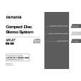
< CD SECTION >
CD PWB
PATTERN SIDE PARTS SIDE
IC2 R2
Q1 R35
RF 23
IC1
R40
VC 5
JW 12
SFR130 FE 1
JW13
IC501
123
IC120
CD Adjustment Method � Perform the adjustments after the machine enters the test mode. � Place the CD mechanism on level ground. � Equipment and tools required Measuring equipment: Oscilloscope (Use the probe of 10:1) Digital Multimeter (Use it in the DC Volt range) Jitter meter (Kikusui 6235) Test Disc: TCD-782 ATD-001 1. Focus Bias Adjustment 1) Connect a digital multimeter to the test point (FE), (VC). 2) Play back the 2nd track of TCD-782. 3) Adjust SFR130 until the digital multimeter indicates 0 ± 10 mV. 2. RF Waveform Check 1) Connect an oscilloscope to test point (RF), (VC). 2) Play back the 2nd track of TCD-782. 3) Check that the RF waveform has the maximum amplitude and the center of the wedge waveform has the clear blank. 3. Jitter Check 1) While an oscilloscope is kept connected in the same test point as in step 2. RF Waveform Check, connect the output terminal of an oscilloscope to the input terminal of the jitter meter. 2) Set the VOLT range selector of an oscilloscope to 500 mV range or lower. 3) Play back the 2nd track of TCD-782. 4) Check that the jitter meter indicates 28.0 ns or less.
RF
DIGITAL MULTIMETER V
FE VC
OSCILLOSCOPE
OUTPUT
Approx. 1.8Vp-p
RF VC
EYE PATTERN must be CLEAR and MAX VOLT / DIV: 500mV TIME / DIV: 0.2µs
0V
OSCILLOSCOPE JITTER METER OUTPUT INPUT ns
4. Play Ability Check 1) Play back the 3rd, 8th, and 13th track of ATD-001. Check that the noise does not occur and sound skipping does not occur. 5. Laser Current Check * Do not perform this measurement unless the laser is suspected to be defective. 1) Connect a digital multimeter across the resistor R2 (10 �). 2) Play back the TCD-782 and check the DC voltage value on the digital multimeter. 3) Calculate the laser current (Iop) by dividing the DC voltage across R2 by the resistor value (R2 = 10 �). Check that the laser current (Iop) is 80 mA or less.
VC
DIGITAL MULTIMETER V
R2 R2
� 43 �
|
|
|
> |
|