|
Dla tego produktu nie napisano jeszcze recenzji!
 ;
Schematy są ale można wysilić się i zrobić kolorowy skan i o większej rozdzielczości. Wtedy schematy płytek będą czytelniejsze. Całość super jako wartość merytoryczna. Wszystkie dane potrzebne do podłączenia różnego rodzajów urządzeń takich gramofon, CD itd.
 ;
Szybko, sprawnie i tanio. Serwis godny polecenia. Będę polecał innym
;
Ogólnie jest OK, z wyjątkiem obrazu płyty głównej, który jest miejscami mało czytelny, ale można sobie poradzić.
;
Dokładna dokumentacja, pomogła w szybkiej naprawie telewizora. Dziękuję!
;
jedyne do czego mogę mieć zastrzeżenie to jakość zdjęć zawartych w przesłanej instrukcji serwisowej ponieważ są fatalnej jakości, praktycznie nieczytelne. tak poza tym jestem zadowolony to jest to czego szukałem.
5
6
7
8
11 12 13 14
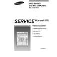
Remove the three screws. Remove the PCB support. Remove the flexible cable and disconnect the connector. Remove the DVDM Assy.
15 16
Connect the two jig cables. Reattatch the three flexible cables(A ) and the one connector (A) from the Table Mechanism Section.
A
17 12
PCB Support
Remove the soldered joint pickup short point. Reattatch the clamper holder by reattatching the two screws.
18
Flexible cable
Cutting Pliers
AF Assy
15
Jig cable (GGD1228)
B
13 13 11
CN923
14
A
13 11
CN5102 CN5101
11
CN911
C
15
DVDM Assy
Jig cable (GGD1160)
To DVDM CN923
To DVDM CN911
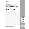
19 20
Insert the insulation sheet between the DVDM Assy and the chassis. Arrange the cables as shown in the photo below.
D
E
19
Insulation sheet
DVDM Assy
F
XV-HTD330
5 6 7 8
121
|