|
|
|
Kategorie
|
|
Informacje
|
|
Polecamy
|
|
|
 |
|
|
Dla tego produktu nie napisano jeszcze recenzji!
 ;
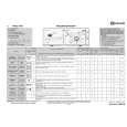
Schematy są ale można wysilić się i zrobić kolorowy skan i o większej rozdzielczości. Wtedy schematy płytek będą czytelniejsze. Całość super jako wartość merytoryczna. Wszystkie dane potrzebne do podłączenia różnego rodzajów urządzeń takich gramofon, CD itd.
 ;
Szybko, sprawnie i tanio. Serwis godny polecenia. Będę polecał innym
;
Ogólnie jest OK, z wyjątkiem obrazu płyty głównej, który jest miejscami mało czytelny, ale można sobie poradzić.
;
Dokładna dokumentacja, pomogła w szybkiej naprawie telewizora. Dziękuję!
;
jedyne do czego mogę mieć zastrzeżenie to jakość zdjęć zawartych w przesłanej instrukcji serwisowej ponieważ są fatalnej jakości, praktycznie nieczytelne. tak poza tym jestem zadowolony to jest to czego szukałem.
1
2
3
4
4 AMP Module L-2CH
1
A
the AMP module L-2CH can be removed without removing the RX module. (Shown as step �.)
2
Remove the two screws.
2
Chassis section
3 4 5 6 7
Remove the three screws. Remove the two push rivets. Remove the one screw. Put off the PCB angle for a while. After removing POWER ASSY by removing one screw, remove the AMP Module L-2CH by removing the three connectors. Barrier
B
3 3
4
3
2
Rear view
7 7 7
C
6
5 7 7
Before shipping out the product, be sure to clean the following positions by using the prescribed cleaning tools: Position to be cleaned Fans
D
PCB Angle
Cleaning tools Cleaning paper : GED-008
Able to input signals using the jumper wire for service. At that time remove the RX MOD ULE. (Refer to 7.1.3 DIAGNOSIS FOR AMP SECTION)
AMP Module L-2CH MAIN Assy
CN3305 CN3306
CN3304
REGULATOR Assy
E
CN3303
CN3301
CN3302
8 8
Jig Cable (GGD1335)
Connect the jig cable (GGD1335).
AMP Assy
Diagnosis
F
62
1 2
XW-DV1WS
3 4
|
|
|
> |
|