|
Dla tego produktu nie napisano jeszcze recenzji!
 ;
Wszystko w porządku.
Instrukcja czytelna i kompletna.
Dziękuję.
all right!
thank you.
;
Bardzo dobra instrukcja. Zawiera wszystko co potrzeba, polecam!
 ;
Instrukcja jest OK. Schematy czytelne, opisane niektóre procedury.
;
Instrukcja bardzo czytelna. zawiera co potrzeba. Polecam
;
...instrukcja serwisowa w pełni czytelna i kompletna. Dziękuję!
103SW/SW-301/1050SW/SW-501
CONTENTS/DISASSEMBLY FOR REPAIR/ADJUSTMENT
Contents
SPECIFICATIONS ........................................Top cover CONTENTS ............................................................... 2 DISASSEMBLY FOR REPAIR....................................2 ADJUSTMENT ............................................................2 PC BOARD ................................................................ 3 SCHEMATIC DIAGRAM ............................................ 5 EXPLODED VIEW ......................................................7 PARTS LIST................................................................8
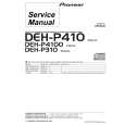
DISASSEMBLY FOR REPAIR
< How to remove the front panel >
1. Remove the decoration plate (1) by a pincette to the bottom of the front panel, then remove the 3 screws (2). 2. 103SW/SW-301: Remove the front panel in the upper slanting direction of the arrow (3). 1050SW/SW-501 : Remove the front panel just the frontwards.
2 x3
3
1
1
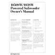
ADJUSTMENT
No. ITEM INPUT SETTINGS OUTPUT SETTINGS AMPLIFIER SETTINGS ALIGNMENT POINTS ALIGN FOR FIG.
Unless otherwise specified, the individual switches should be set as following : POWER : ON NO SIGNAL INPUT 1 IDLE CURRENT � Connect a DC voltmeter to R611
(a)
VOLUME : 0
VR601
5 mV
(a)
Dc voltmeter
5 mV
R611
2
|