|
|
|
Kategorie
|
|
Informacje
|
|
Polecamy
|
|
|
 |
|
|
Dla tego produktu nie napisano jeszcze recenzji!
 ;
Ogólnie jest OK, z wyjątkiem obrazu płyty głównej, który jest miejscami mało czytelny, ale można sobie poradzić.
 ;
Dokładna dokumentacja, pomogła w szybkiej naprawie telewizora. Dziękuję!
 ;
jedyne do czego mogę mieć zastrzeżenie to jakość zdjęć zawartych w przesłanej instrukcji serwisowej ponieważ są fatalnej jakości, praktycznie nieczytelne. tak poza tym jestem zadowolony to jest to czego szukałem.
 ;
Wszystko w porządku.
Instrukcja czytelna i kompletna.
Dziękuję.
all right!
thank you.
 ;
Bardzo dobra instrukcja. Zawiera wszystko co potrzeba, polecam!
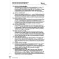
TROUBLE SHOOTING TABLE (Continued)
LED LIGHT NO NORMAL SOUND
comes No sound from the
Check F4701. F3700. out at AV-out J905 speaker
Normal Blown out
Set volume to maximum. Is there any sound output signal at pin 10 & 14 of IC 301 ?
Check sound output signal from No Yes pin 92 & 93 of IC 2100 and its if there Check related circuit. is sound input connection to
Replace the Fuse.
No signal at pin 2 the speaker Yes
Is the Fuse again blown out? & 21 of IC 301.
No
Check output main unit ? consisting of IC701, IC702,
Does STBY+5V appear at pin 1 P1001 Check the power circuit T701 and its related parts. signal at pin
68, 69 of IC 2100 and its
19
19-1 19-2
No Yes
the power Check 3V output related circuit. circuit at the front from pin 22 of IC unit consisting of 2100 and its IC4702, IC4701, related parts. D4707 and its related parts.
29H-FD5RU
|
|
 |
> |
|
