|
|
|
Kategorie
|
|
Informacje
|
|
Polecamy
|
|
|
 |
|
|
Dla tego produktu nie napisano jeszcze recenzji!
 ;
Wszystko w porządku.
Instrukcja czytelna i kompletna.
Dziękuję.
all right!
thank you.
;
Bardzo dobra instrukcja. Zawiera wszystko co potrzeba, polecam!
 ;
Instrukcja jest OK. Schematy czytelne, opisane niektóre procedury.
;
Instrukcja bardzo czytelna. zawiera co potrzeba. Polecam
;
...instrukcja serwisowa w pełni czytelna i kompletna. Dziękuję!
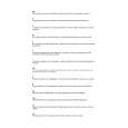
CUT-OFF, BACKGROUND AND SUB-CONTRAST ADJUSTMENT
No. point Adjusting procedure/conditions Waveform and others
1 CRT CUTOFF Pattern" signal. * Befor doing adjustment, make sure the 4 MAX BEAM 1. Receive E-5CH "Monoscope pattern" with stand-
(CUTOFF 2. Select P-NORM with remote controller. R/G/B-cut and the B/G-Drive is at initial R1759 ard mode.
3. Turn on service switch, and select CUT 2. Make pictur normal with the remote BKGD) value.
SERVICE OFF BKGD mode at the service mode. controller.(AV MODE: DYNAMIC) MODE I C BUS 4. Select screen VR 0/10. 3. Connect the beam ammeter between TP1601 & 2
DATA ADJUST5. Press "-/--" key of the remote controller to select TP1602. MENT the horizontal centering mode. Ammeter full scale-3mA range
6. Turn scteen VR clockwise, and adjust first TP1602 is connected at side of the amme-
lighting horizontal centering rasterslighly light. ter.
7. Adjust CUT OFF data two other colors, and TP1601 is connected at + side of the amme-
coarsely adjust the horizontal centering to become ter. white. (Note 1) 4. Adjust the beam current to 1.8mA ± 20µA with On the monocolor screen of white or green.
8. Turn screen VR in the opposite direction to R1759 (sub-contrast VR).
point where horizontal centering raster Note : Apply adjustment after aging with the beam goes out. current 1,600±50µA more for 30 min or more. Note 1: Apply adjustment after aging with (On the white or green monocolor screen) beam current 1,600±50µA more for 30 min or more. 5 SUB-CON1. Receive the window pattern with AV input. Note 3: 9. Press "-/--" key of the remote controller to select TRAST (SUB2. Make picture normal with the remote controlUse "Y" of Minolta color analyzer the normal mode.
2
CONT) I C ler. (AV MODE: DYNAMIC) CA-100 in adjustment.
BUS ADJUST3. Select the SUB-CONTRAST adjustment mode Note 4:
2 WHITE BAL1. Receive E-5CH "Monoscope Pattern" signal. Note1: MENT (AV with remote controller, and adjust 50% white Use PAL window pattern of the 6 SUB-CON1. Select the DVD mode. (CUT TP1602. G CUT OFF UP "2"KEY CONT DVD) (Component signal) (Window pattern) BUS ADJUST1.8mA with R1622 (Sub-Contrast VR) B CUT OFF UP "3"KEY 50% white for SUB-CONT I C BUS 3. Make picture normal with the remote control2 (DVD SIGNAL) 4. Select the SUB-CONTRAST adjustment mode tor.) above comparison.
ANCE BACK2. Select P-NORM with the remote controller. R CUT OFF UP "1"KEY SIGNAL) to 165 ± 10cd. signal generator for adjustment. GROUND 3. Connect the beam ammeter between TP1601 DOWN "4"KEY (PAL and colour burst are provided.)
2
TRAST (SUB2. Receive of the DVD signal generator. BKGD) I C 4. Coarsely adjust the beam current to approx. DOWN "5"KEY Note 5:Window Pattern
11
2
MENT (AV 5. Receive the window pattern with AV input. DOWN "6"KEY SIGNAL) (PAL burst generated signal generaData up/down is possible with the ADJUSTMENT ler. (AV MODE: DYNAMIC)
(DVD) with the remote controller, and adjust 50% 6. With data of G-drive and B-drive, adjust the *12,300°K X : 0.272 ± 0.005 Dark white for white to 165 ± 10 cd. color temperature 12,300°K of the white peak to Y : 0.275 ± 0.005 SUB-BRIGHT * When E-2 CH (Crosshatch pattern) 12,300°K with R-cut off, G-cut off and B-cut off. Note1: NESS (SUB2. Make picture normal with the remote controlor equivalent signal is received. BRI) I C BUS ler. CONTROL(AV 3. Select SUB-BRIGHT adjustment mode 1.Make image normal with the 9. Check 12,300°K at the low white. DOWN " "KEY SIGNAL) controller, and adjust the right dark remote controller. Note1 : Apply this adjustment after aging with the B-DRIVE UP "8"KEY white area of window pattern to 5.5 ± 0.5 cd. 2.Adjust 3rd (1 thru 5 from the beam current 1,600±50µA more for 30 min or DOWN "0"KEY sink. (On the white or green minocolor screen) above comparison. NESS (SUB2. Receive of the DVD signal generator. 8. Read just color temperature at the white peak. G-DRIVE UP "7"KEY
7. Adjust right dark area of the window to 100) 7 SUB-BRIGHT1. Receive the window pattern with AV input. Reference:
white. (With Minolta color thermometer CA-
more. Data up/Down is possible with the left) black of the window pattern to 8 SUB-BRIGHT1. Select the DVD mode.
* The color temperature is based on the shipment 2 BRI DVD) I C (Component signal) (Window pattern)
initial setting table. BUS CON3. Make picture normal with the remote controlTROL (DVD ler. (AV MODE: DYNAMIC) SIGNAL) 4. Select the SUB-BRIGHT adjustment mode (DVD) white area of the window pattern to 5.5 ± 0.5 cd of window pattern. with remote controller, and adjust the right dark
3 WHITE BAL1. The window pattern is received with DVD signal Note2: CUT OFF POINT
ANCE BACK(component signal). Use window pattern of the sigGROUND 2. Apply adjustment in the same manner as item nal generator for adjustment. (CUT OFF DVD 5 of adjustment 2 and the subsequence above. BKGD) I C (17,000°K or 18,000°K) (G-DRIVE, B-DRIVE, R2 signal generator.) MENT (DVD Apply after the end of adjustment
BUS ADJUSTCUT G-CUT OFF, B-CUT OFF) (PAL, colour burst is generated with
SIGNAL) 2.
29WF30
11-1 11-2
|
|
|
> |
|