|
|
|
Kategorie
|
|
Informacje
|
|
Polecamy
|
|
|
 |
|
|
Dla tego produktu nie napisano jeszcze recenzji!
 ;
jedyne do czego mogę mieć zastrzeżenie to jakość zdjęć zawartych w przesłanej instrukcji serwisowej ponieważ są fatalnej jakości, praktycznie nieczytelne. tak poza tym jestem zadowolony to jest to czego szukałem.
 ;
Wszystko w porządku.
Instrukcja czytelna i kompletna.
Dziękuję.
all right!
thank you.
;
Bardzo dobra instrukcja. Zawiera wszystko co potrzeba, polecam!
;
Instrukcja jest OK. Schematy czytelne, opisane niektóre procedury.
;
Instrukcja bardzo czytelna. zawiera co potrzeba. Polecam
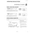
AV-14F1P
STANDARD CIRCUIT DIAGRAM
s NOTE ON USING CIRCUIT DIAGRAMS
1. SAFETY
The components identified by the ! symbol and shading are critical for safety. For continued safety replace safety critical components only with manufactures recommended parts. q Type No indication MY MM PP MPP MF TF BP TAN (3) Coils No unit Others (4) Power Supply : Ceramic capacitor : Mylar capacitor : Metalized mylar capacitor : Polypropylene capacitor : Metalized polypropylene capacitor : Metalized film capacitor : Thin film capacitor : Bipolar electrolytic capacitor : Tantalum capacitor : [µH] : As specified : B1 : 12V : 9V : 5V * Respective voltage values are indicated. (5) Test point : Test point : Only test point display (6) Connecting method : Connector : Wrapping or soldering : Receptacle : [�] : [K�] : [M�] (7) Ground symbol # " : LIVE side ground : ISOLATED (NEUTRAL) side ground : EARTH ground : DIGITAL ground
2. SPECIFIED VOLTAGE AND WAVEFORM VALUES
The voltage and waveform values have been measured under the following conditions. (1) Input signal : Color bar signal (2) Setting positions of each knob/button and variable resistor : Original setting position when shipped (3) Internal resistance of tester : DC 20k�/V (4) Oscilloscope sweeping time : H :V © 20µS/div © 5mS/div
: Others © Sweeping time is specified. (5) Voltage values : All DC voltage values * Since the voltage values of signal circuit vary to some extent according to adjustments, use them as reference values.
3. INDICATION OF PARTS SYMBOL [EXAMPLE]
q In the PW board : R1209 © R209
4. INDICATIONS ON THE CIRCUIT DIAGRAM
(1) Resistors q Resistance value No unit K M
q Rated allowable power No indication : 1/4 [W] Others : As specified q Type No indication OMR MFR MPR : Carbon resistor : Oxide metal film resistor : Metal film resistor : Metal plate resistor
5. NOTE FOR REPAIRING SERVICE
This model�s power circuit is partly different in the GND. The difference of the GND is shown by the LIVE : (#) side GND and the ISOLATED (NEUTRAL) : (") side GND. Therefore, care must be taken for the following points. (1) Do not touch the LIVE side GND or the LIVE side GND and the ISOLATED (NEUTRAL) side GND simultaneously. If the above caution is not respected, an electric shock may be caused. Therefore, make sure that the power cord is surely removed from the receptacle when, for example, the chassis is pulled out. (2) Do not short between the LIVE side GND and ISOLATED (NEUTRAL) side GND or never measure with a measuring apparatus (oscilloscope, etc.) the LIVE side GND and ISOLATED (NEUTRAL) side GND at the same time. If the above precaution is not respected , a fuse or any parts will be broken. q Since the circuit diagram is a standard one, the circuit and circuit constants may be subject to change for improvement without any notice.
UNFR : Non-flammable resistor FR : Fusible resistor * Composition resistor 1/2 [W] is specified as 1/2S or Comp. (2) Capacitors q Capacitance value 1 or higher : [pF] less than 1 : [µF] q Withstand voltage No indication AC indicated Others : DC50 [V] : AC withstand voltage [V] : DC withstand voltage [V]
* Electrolytic Capacitors 47/50 [Example]: Capacitance value [µF]/withstand voltage [V]
No. 56084
2-3
|
|
|
> |
|