|
Dla tego produktu nie napisano jeszcze recenzji!
 ;
Dokładna dokumentacja, pomogła w szybkiej naprawie telewizora. Dziękuję!
 ;
jedyne do czego mogę mieć zastrzeżenie to jakość zdjęć zawartych w przesłanej instrukcji serwisowej ponieważ są fatalnej jakości, praktycznie nieczytelne. tak poza tym jestem zadowolony to jest to czego szukałem.
;
Wszystko w porządku.
Instrukcja czytelna i kompletna.
Dziękuję.
all right!
thank you.
;
Bardzo dobra instrukcja. Zawiera wszystko co potrzeba, polecam!
;
Instrukcja jest OK. Schematy czytelne, opisane niektóre procedury.
5
6
7
8
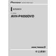
7. DISASSEMBLY
- Removing the Monitor Assy (Fig.1) Remove the Case. Case
A
1
Remove the four screws.
1
1
Detach two hooks on the tip of a white arrow. Disconnect the cable and then remove the Monitor Assy.
Fig.1
1
Monitor Assy
1
- Removing the LCD Assy (Fig.2) Disconnect the two Cables.
LCD Assy
Cable
B
1
Remove the four screws.
1
1
Detach two Hooks on the tip of a white arrow. Lift the LCD Assy forward, detach lower three hooks and then remove the LCD Assy.
1
Hook
1
Fig.2
C
- Removing the Monitor PCB and Invertor PCB(Fig.3) Disconnect the Cable(1).
Holder
3
Invertor PCB
3 4 1
1 2
Remove the two screws.
Straighten the tab at location indicated.
4
Disconnect the Cable(2) and then remove the Invertor PCB.
4 3 4
Remove the two screws and then remove the Holder. Remove the four screws. Cable(3)
Cable(1)
4
2
D
1
Fig.3
Moniter PCB
Cable(1)
Cable(2)
Disconnect the Cable(3) and then remove the Monitor PCB.
Knob Unit
- Removing the Keyboard Unit (Fig.4,5) Fig.4 Remove the Knob Unit.(Fig.4)
E
1
Remove the three screws.(Fig.5)
1 1
1
Fig.5
Disconnect the Cable and then remove the Keyboard Unit.(Fig.5) Cable Keyboard Unit
F
AVH-P4050DVD/XNCN5
5 6
7
8
63
|