|
Dla tego produktu nie napisano jeszcze recenzji!
 ;
Schematy są ale można wysilić się i zrobić kolorowy skan i o większej rozdzielczości. Wtedy schematy płytek będą czytelniejsze. Całość super jako wartość merytoryczna. Wszystkie dane potrzebne do podłączenia różnego rodzajów urządzeń takich gramofon, CD itd.
 ;
Szybko, sprawnie i tanio. Serwis godny polecenia. Będę polecał innym
;
Ogólnie jest OK, z wyjątkiem obrazu płyty głównej, który jest miejscami mało czytelny, ale można sobie poradzić.
;
Dokładna dokumentacja, pomogła w szybkiej naprawie telewizora. Dziękuję!
;
jedyne do czego mogę mieć zastrzeżenie to jakość zdjęć zawartych w przesłanej instrukcji serwisowej ponieważ są fatalnej jakości, praktycznie nieczytelne. tak poza tym jestem zadowolony to jest to czego szukałem.
5
6
7
8
-
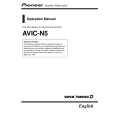
Removing the Display Assy (Fig.8)
Holder
Display Assy
A
1 2 3
Remove the two screws and then remove the Holder. Remove the four screws and then remove the Cover Unit. Remove the four screws.
1 3
1 3
Disconnect the connector and then remove the Display Assy.
3 2 2 2 2
3
B
Cover Unit
- Removing the Monitor PCB (Fig.9)
Fig.8
1 2
Straighten the tabs at two locations indicated.
1
1
C
Remove the screw.
Disconnect the connector and then remove the Monitor PCB.
2
D
Monitor PCB
Fig.9
E
F
AVIC-N4/XU/UC
5 6 7 8
115
|