|
|
|
Kategorie
|
|
Informacje
|
|
Polecamy
|
|
|
 |
|
|
Dla tego produktu nie napisano jeszcze recenzji!
 ;
Dokładna dokumentacja, pomogła w szybkiej naprawie telewizora. Dziękuję!
 ;
jedyne do czego mogę mieć zastrzeżenie to jakość zdjęć zawartych w przesłanej instrukcji serwisowej ponieważ są fatalnej jakości, praktycznie nieczytelne. tak poza tym jestem zadowolony to jest to czego szukałem.
;
Wszystko w porządku.
Instrukcja czytelna i kompletna.
Dziękuję.
all right!
thank you.
;
Bardzo dobra instrukcja. Zawiera wszystko co potrzeba, polecam!
;
Instrukcja jest OK. Schematy czytelne, opisane niektóre procedury.
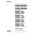
2-8. R Signal De-matrix Adjustment 2-9. G Signal De-matrix Adjustment
2-8. R Signal De-matrix Adjustment
Measurement equipment Waveform monitor Procedure 1. Check to see that S505 is set to RGB. 2. Supply 100% color bars signal from the signal generator to the SDI IN connector. 3. Set the waveform monitor as follows. MODE : WAVEFORM INPUT : CH3 REF : EXT 4. Adjust 1RV305 so that the level A satisfies the specification. Use 1RV303 in the fine adjustment so that the peak of each level is flat. n Do not set S505 to YUV until �2-9. G Signal Dematrix Adjustment� is completed. Measuring point : R-Y/R connector (BKPF-102CB connector panel) Adjustment point : 1RV303 (F-6)/DAC-30 (for fine adjustment) 1RV305 (H-6)/DAC-30
2-9. G Signal De-matrix Adjustment
n Adjust the G signal after the B signal (section 2-7) and R signal (section 2-8) adjustments are completed. Measurement equipment Waveform monitor Procedure 1. Check to see that S505 is set to RGB. 2. Supply 100% color bars signal from the signal generator to the SDI IN connector. 3. Set the waveform monitor as follows. MODE : WAVEFORM INPUT : CH1 REF : EXT 4. Adjust 1RV404 so that the level A satisfies the specification. 5. Set S505 to YUV. Measuring point : Y/G connector (BKPF-102CB connector panel) Adjustment point : 1RV404 (H-5)/DAC-30
A A
A = 700 ±14 mV p-p A = 700 ±14 mV p-p
BKPF-102CB
2-5 (E)
|
|
|
> |
|