|
|
|
Kategorie
|
|
Informacje
|
|
Polecamy
|
|
|
 |
|
|
Dla tego produktu nie napisano jeszcze recenzji!
 ;
jedyne do czego mogę mieć zastrzeżenie to jakość zdjęć zawartych w przesłanej instrukcji serwisowej ponieważ są fatalnej jakości, praktycznie nieczytelne. tak poza tym jestem zadowolony to jest to czego szukałem.
 ;
Wszystko w porządku.
Instrukcja czytelna i kompletna.
Dziękuję.
all right!
thank you.
;
Bardzo dobra instrukcja. Zawiera wszystko co potrzeba, polecam!
;
Instrukcja jest OK. Schematy czytelne, opisane niektóre procedury.
;
Instrukcja bardzo czytelna. zawiera co potrzeba. Polecam
TABLE OF CONTENTS 1. SERVICE NOTE ................................................................. 3 2. GENERAL ............................................................................ 4 3. DISASSEMBLY
3-1. Cabinet (Rear) Sub Assy ..................................................... 5 3-2. Main Board ......................................................................... 5 3-3. MD Assy ............................................................................. 5
6. EXPLODED VIEWS
6-1. Cabinet Section ................................................................. 20 6-2. MD Section ....................................................................... 22
7. ELECTRICAL PARTS LIST......................................... 23
4. ELECTRICAL ADJUSTMENTS ................................... 6 5. DIAGRAMS
5-1. 5-2. 5-3. 5-4. 5-5. IC Pin Descriptions ............................................................. 7 Block Diagram .................................................................... 9 Printed Wiring Board ........................................................ 12 Schematic Diagram �Main Section (1/2)� ........................ 15 Schematic Diagram �Main Section (2/2)� ........................ 17
SECTION 1 SERVICE NOTE
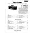
NOTES ON HANDLING THE OPTICAL PICK-UP BLOCK OR BASE UNIT The laser diode in the optical pick-up block may suffer electrostatic breakdown because of the potential difference generated by the charged electrostatic load, etc. on clothing and the human body. During repair, pay attention to electrostatic breakdown and also use the procedure in the printed matter which is included in the repair parts. The flexible board is easily damaged and should be handled with care. NOTES ON LASER DIODE EMISSION CHECK The laser beam on this model is concentrated so as to be focused on the disc reflective surface by the objective lens in the optical pick-up block. Therefore, when checking the laser diode emission, observe from more than 30 cm away from the objective lens. Before Replacing the Optical Pick-Up Block Please be sure to check throughly the parameters as par the �Optical Pick-Up Block Checking Procedures� (Part No.: 9-960-027-11) issued separately before replacing the optical pick-up block. Note and specifications required to check are given below. � FOK output : IC501 @� pin When checking FOK, remove the lead wire to disc motor. � S curve P-to-P value : 2.0Vp-p IC501 $� pin When checking S curve P-to-P value, remove the lead wire to disc motor. � RF signal P-to-P value : 0.6 - 1.3Vp-p � Traverse signal P-to-P value : 0.8 - 2.8Vp-p � The repairing grating holder is impossible. Precautions for Checking Emission of Laser Diode Laser light of the equipment is focused by the objective lens in the optical pick-up so that the light focuses on the reflection surface of the disc. Therefore, be sure to keep your eyes more than 30 cm apart from the objective lens when you check the emission of laser diode. Laser Diode Checking Methods During normal operation of the equipment, emission of the laser diode is prohibited unless the upper lid is closed while turning ON the S808 (push switch type). The following checking method for the laser diode are operable. Emission of the laser diode is visually checked 1. Open the upper lid. 2. Push the S808 as shown in Fig. 1. 3. Check the objective lens for confirming normal emission of the laser diode. If not emitting, there is a trouble in the automatic power control circuit or the optical pick-up. During normal operation, the laser diode is turned ON about 2.5 seconds for focus searching.
S808
Fig. 1 Method to push the S808
�3�
|
|
|
> |
|