|
|
|
Kategorie
|
|
Informacje
|
|
Polecamy
|
|
|
 |
|
|
Dla tego produktu nie napisano jeszcze recenzji!
 ;
Bardzo dobra jakość skanu, przystępna cena. Instrukcja serwisowa okazała się przydatna przy "reanimowaniu" dwudziestoparoletniego decka, który teraz pięknie gra :)
;
...instruction is ok.
...instrukcja jest ok.
Thanks/Dzięki
;
Documentation made available quickly and It is good quality. Thanks.
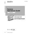
4-13. TG1 Arm, Reel Table (S) Assembly, Push Switch (3Key)
1. Removal procedure
1) 2) 3) 4) 5) 6) 7) 8) 9) Remove the TG1 arm spring 1.
Note: Take note of the position where the spring has been hooked.
2. Attachment procedure
Attach the push switch (3key) qa to the cassette guide T qs with the two claws 0. 2) Attach the cassette guide T qs to the notch of the LS chassis block assembly with the two claws 9. 3) Solder the cassette guide T qs to the LS-057 board at the four locations. 4) Attach the lock guide 7. 5) Attach the BT band assembly 6. 6) Check the location of the reel table S 4. Then, rotate the S ratchet arm 3 in the direction of the arrow A and insert the band of the BT band assembly 6 into the groove on the side. 7) Attach the BT band assembly to the TG1 arm 2 and attach it to the mechanism chassis block assembly. 8) Check the shape of the hook of the TG1 arm spring 1. Hook one end of the spring on the TG1 arm 2. Then, hook the other end of the spring on the same location of the LS chassis block assembly where you have taken note when the spring is removed. 9) Attach the RVS arm spring. 10) Check the TG1 back-tension. (Refer to 5-1.)
Note: The BT band assembly 5 must be completely inserted into the groove on the side of the reel table (S) 4.
1)
Remove the TG1 arm 2. Open the claw of the reel table (S) assembly 4 in the directions of the arrows B and C and remove the reel table S assembly. Remove the RVS arm spring 5. Rotate the S ratchet arm 3 in the direction of the arrow A and remove the BT band assembly 6. Remove the lock guide 7. Remove the four solderings of the LS-057 board. Remove the two claws 9 of the cassette guide T qs from the notch of the LS chassis. Remove the push switch (3key) qa by releasing the two claws of the cassette guide T qs.
B
4 Reel table (S) assembly
Check the location of the reel table (S) assembly.
Reel table (S) assembly is at right angles. Thin
Open the claw of the reel table S in the directions of the arrows B and C.
C
7 Lock guide
qa Push switch (3key) (REC proof) 2 TG1 arm
When attaching it, insert it under the LS chassis assembly.
6 BT band assembly Never coat grease, never attach any
foreign materials nor bend the assembly. Fit here.
5 RVS arm spring 1 TG1 arm spring qs Cassette guide T
9 Two claws
Reel table (S) assembly
Double-hook side
0 Two claws 8 Remove the four solderings
BT band assembly
RVS arm spring Double-hook side TG1 arm TG1 arm spring
Mechanism status before removing the parts.
A 3 Rotate the S ratchet arm in the direction of the arrow A.
When attaching it, coat the hatched portion with grease.
Fig. 4-13.
� 26 �
|
|
|
> |
|