|
|
|
Kategorie
|
|
Informacje
|
|
Polecamy
|
|
|
 |
|
|
Dla tego produktu nie napisano jeszcze recenzji!
 ;
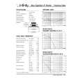
jedyne do czego mogę mieć zastrzeżenie to jakość zdjęć zawartych w przesłanej instrukcji serwisowej ponieważ są fatalnej jakości, praktycznie nieczytelne. tak poza tym jestem zadowolony to jest to czego szukałem.
 ;
Wszystko w porządku.
Instrukcja czytelna i kompletna.
Dziękuję.
all right!
thank you.
;
Bardzo dobra instrukcja. Zawiera wszystko co potrzeba, polecam!
;
Instrukcja jest OK. Schematy czytelne, opisane niektóre procedury.
;
Instrukcja bardzo czytelna. zawiera co potrzeba. Polecam
Diagnostic Software
The paths that are available for video routing and their description(Europe version): Path ID 00 01 02 03 04 05 06 07 08 09 10 11 12 13 14 15 16 17 18 19 20 21 Description
DVDR880-890 /0X1
5.
EN 59
Input signal is VIDEO(CVBS) from digital board and will be re-routed back to the digital board. Input signal is from FRONT VIDEO(CVBS) IN and will be routed to the digital board. No Routing. Input signal is from FRONT S-VIDEO(Y/C) and will be routed to the digital board. No Routing. Input signal is CVBS from SCART1 and will be routed to the digital board. Input signal is CVBS from SCART2 and will be routed to the digital board. Input Signal is CVBS from Digital Board and it will be routed to Scart1 and Scart2. Input signal is VIDEO(CVBS) from ANTENNA IN and will be routed to SCART2. Input signal is VIDEO(CVBS) from SCART1 and will be routed to SCART2. Input signal is VIDEO(CVBS) from SCART2 and will be routed to SCART1. Signal path is routed Fast Blank from Scart2 pin16 and will be routed Scart1 pin16 Input Signal is YC from Digital Board and it will be routed to Scart1. No Routing. No Routing. Input Signal is CVBS from TUNER and it will be routed to Digital . No Routing. Input Signal is routed from digital board YC to REAR S-VIDEO(YC) OUT Signal path is routed from digital board RGB to RGB SCART1 and from digital board CVBS to digital board CVBS. No Routing. Input RGB Signal is routed from Digital Board to SCART1(RGB),Input CVBS Signal from Digital Board to Digital Board and Fast Blanking Signal from Scart 2 to Scart1. Input Y/C Signal from Digital Board is routed to Rear Y/C Connector and Input Y/c Signal from Front Y/C connector is routed to Digital Board.
The paths that are available for video routing and their description (Nafta region): PATH ID 00 DESCRIPTION Input signal is VIDEO(CVBS) from digital board and will be re-routed back to the digital board.A Cinch Cable need to be connected from Rear Cinch Out to Front Cinch In for this Test.(Direct routing on analogue board from YUV In to YUV Out is not Possible) Input signal is from FRONT VIDEO(CVBS) IN and will be routed to the digital board.This routing is same as the above path id. Input signal is from REAR VIDEO(CVBS) IN and will be routed to the digital board. Input signal is from FRONT S-VIDEO(Y/C) IN and the signal received will be routed to the digital board. Input signal is from REAR S-VIDEO(Y/C) IN and will be routed to the digital board. No Routing. No Routing. No Routing. Input signal is VIDEO(CVBS) from TUNER and will be routed to Y Pin of Rear Y/C Connector.This will give only black/White Picture . Input signal is from YUV IN and will be routed to YUV OUT.This is possible only if Digital Board routes back YUV signal received back to the Analogue board(DENC) No Routing. No Routing. No Routing. No Routing. No Routing Input CVBS Signal from Tuner is routed to Digital Board.. No Routing Input RGB Signal is routed from Digital Board to RGB Rear Out and Input CVBS Signal is routed from Rear Cinch In 1 to Digital Board(This second step is for routing Input CVBS Signal from Digital Board to Digital Board again - A Cinch cable need to be connected from Rear Cinch Out1 to Rear Cinch In 1 ) Input Signal from CVBS Rear In is routed to Digital Board.This is same as path id 02. Input Y/C signal from Digital Board is routed to Y/C Rear Out Connector and Input signal from Y/C Rear In Connector is routed to Y/C Digital Board.
01 02 03 04 05 06 07 08 09 10 11 12 13 14 15 16 17
18 19
|
|
|
> |
|