Nie masz w koszyku żadnych produktów
 
English Polski Spanish 
Szukaj instrukcji do
 

(e.g. AA-V20EG JVC, ZX-7 Sony )
PayPal 1000+ rating Secure, Encrypted Checkout.
 
Kto jest w sklepie?
Sklep przegląda 5458 gości 
Kategorie
Informacje
Polecamy
Strona główna >> JVC >> EXA1 Instrukcja Serwisowa
 
 0 szt. w koszyku 

JVC EXA1
Instrukcja Serwisowa


Tweetnij o tym produkcie a dostaniesz $1.00 rabatu!
  • Zawiera schematy
  • Plik do pobrania
  • Format PDF
  • Kompletna instrukcja
  • Język: English
Cena: $4.99

Opis JVC EXA1 Instrukcja Serwisowa

Kompletna instrukcja serwisowa w formie pliku PDF. Instrukcje serwisowe zazwyczaj zawierają schematy, diagramy drukowanych obwodów (PCB), schematy połączeń, schematy blokowe oraz katalog części. Instrukcje serwisowe są wykorzystywane glównie przez osoby naprawiające uszkodzony sprzęt.

Jeśli chcesz się dowiedzieć jak się obsługuje Twój telewizor, magnetowid, odtwarzacz mp3 itp. powinieneś raczej szukać instrukcji obsługi

Instrukcja jest dostępna w następujących językach:

Plik nie jest jeszcze gotowy
Musisz najpierw dokonać zakupu.

Recenzje produktu
Dla tego produktu nie napisano jeszcze recenzji!
Recenzje innych produktów
 SA-A30E AIWA Instrukcja Serwisowa by Adam Grążka;
Wszystko w porządku. Instrukcja czytelna i kompletna. Dziękuję. all right! thank you.
 KX990SR KENWOOD Instrukcja Serwisowa by Viktor Kapeć;
Bardzo dobra instrukcja. Zawiera wszystko co potrzeba, polecam!
 TA2760 ONKYO Instrukcja Serwisowa by Viktor Kapeć;
Instrukcja jest OK. Schematy czytelne, opisane niektóre procedury.
 26PF3302/10 PHILIPS Instrukcja Serwisowa by Ryszard Burzak;
Instrukcja bardzo czytelna. zawiera co potrzeba. Polecam
 DX666 AIWA Instrukcja Serwisowa by Adam Grążka;
...instrukcja serwisowa w pełni czytelna i kompletna. Dziękuję!

Tekstowy podgląd strony 7 (kliknij aby zobaczyć)
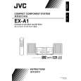
SECTION 3 DISASSEMBLY
3.1 Main body section 3.1.1 Removing the top cover (See Fig.1) (1) From the top side of the main body, remove the four screws A attaching the top cover.

A

Top cover

A

A
Fig.1 3.1.2 Removing the AL panel L and AL panel R (See Figs.2 to 7.) � Remove the top cover. (1) Remove the two screws B, screw C and screw C' attaching the bridge A. (See Fig.2.) Reference: When attaching the screw C' attach the lug wire with it. (See Fig.2.) (2) Remove the two screws C attaching the bridge B. (See Fig.2.) (3) Remove the screw C and screw C' attaching the bridge C. (See Fig.2.) Reference: When attaching the screw C' attach the lug wire with it. (See Fig.2.) From the back side of the main body, remove the three screws D attaching the bridge C. (See Fig.3.) From the top side of the main body, remove the two screws E attaching the AL panel L and AL panel R. (See Fig.4.) From the bottom side of the main body, remove the three screws F attaching the wood bar. (See Fig.5.) Remove the six screws G and two screws H attaching the AL panel L and AL panel R. (See Fig.6.) Remove the AL panel L and AL panel R in the direction of the arrow 2 while extending the back section of the AL panel L and AL panel R in the direction of the arrow 1. (See Fig.7.)

Bridge C Lug wire Bridge B

C'

C

C

C

(4) (5) (6) (7) (8)

C'

C

Bridge A
Fig.2

B

(No.MB150)1-7

Klienci kupując ten produkt kupili także

$4.99

EX-A1 JVC
Instrukcja Obsługi

Kompletna instrukcja obsługi w formie pliku PDF. Plik PDF zostanie dostarczony na Twój adres email…
>
Parse Time: 0.173 - Number of Queries: 108 - Query Time: 0.042