|
|
|
Kategorie
|
|
Informacje
|
|
Polecamy
|
|
|
 |
|
|
Dla tego produktu nie napisano jeszcze recenzji!
 ;
Schematy są ale można wysilić się i zrobić kolorowy skan i o większej rozdzielczości. Wtedy schematy płytek będą czytelniejsze. Całość super jako wartość merytoryczna. Wszystkie dane potrzebne do podłączenia różnego rodzajów urządzeń takich gramofon, CD itd.
 ;
Szybko, sprawnie i tanio. Serwis godny polecenia. Będę polecał innym
;
Ogólnie jest OK, z wyjątkiem obrazu płyty głównej, który jest miejscami mało czytelny, ale można sobie poradzić.
;
Dokładna dokumentacja, pomogła w szybkiej naprawie telewizora. Dziękuję!
;
jedyne do czego mogę mieć zastrzeżenie to jakość zdjęć zawartych w przesłanej instrukcji serwisowej ponieważ są fatalnej jakości, praktycznie nieczytelne. tak poza tym jestem zadowolony to jest to czego szukałem.
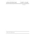
3.1.8 Removing the digital amplifier board (See Fig.11) � Prior to performing the following procedures, remove the rear cover, bottom case (A), bottom case (B) and top case assembly. (1) From the left side of the main body, disconnect the wire from the connector CN301 on the digital amplifier board. (2) Remove the spacer and tie band fixing the wire. (3) Remove the two screws K, two screws L and screw L' attaching the digital amplifier board. (4) Pull the digital amplifier board toward this side, disconnect the connectors CN961 and CN981 on the digital amplifier board. Reference : � When attaching the screw L', attach the earth wire together it. � After connecting the wire, fix the wire with the spacer and tie band.
Digital amplifier board
Tie band
K
CN981 CN961 Spacer
K
Wire
Earth Wire
CN301
L
L'
Fig.11
L
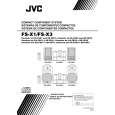
3.1.9 Removing the power supply board (See Figs.12 to 14) � Prior to performing the following procedures, remove the rear cover, bottom case (A), bottom case (B), top case assembly, tuner, function board, micon board and digital amplifier board. (1) From the top side of the main body, remove the two screws M attaching the center chassis. (See Fig.12.) (2) From the bottom side of the main body, remove the two screws N attaching the power supply board. (See Fig.13.) (3) Disconnect the card wire from the connector CN903 on the power supply board. (See Fig.14.) (4) Remove the three screws P attaching the power supply board. (See Fig.14.) (5) Remove the barrier (E) and barrier (F) under the power supply board. (See Fig.14.) Reference : � Before attaching the each parts, pass the card wire through the holes f on the center chassis. � After attaching the center chassis, put the earth wire through the slit g of the power supply board and sections h of the center chassis.
N
Power supply board
N
Fig.13
Bottom chassis
Card wire
Hole f
Center chassis
P
Power supply board Card wire
M M P
Bottom chassis Earth wire Slit g
Fig.12
Section h
Barrier (E) Barrier (F)
P
Fig.14
CN903
1-12 (No.MB004)
 $4.99 FS-X1 JVC
Katalog Części Katalog części w formie pliku PDF. Plik zawiera wykaz części znajdujących się w urządzeniu wr…
|
|
|
> |
|