|
|
|
Kategorie
|
|
Informacje
|
|
Polecamy
|
|
|
 |
|
|
Dla tego produktu nie napisano jeszcze recenzji!
 ;
Schematy są ale można wysilić się i zrobić kolorowy skan i o większej rozdzielczości. Wtedy schematy płytek będą czytelniejsze. Całość super jako wartość merytoryczna. Wszystkie dane potrzebne do podłączenia różnego rodzajów urządzeń takich gramofon, CD itd.
 ;
Szybko, sprawnie i tanio. Serwis godny polecenia. Będę polecał innym
;
Ogólnie jest OK, z wyjątkiem obrazu płyty głównej, który jest miejscami mało czytelny, ale można sobie poradzić.
;
Dokładna dokumentacja, pomogła w szybkiej naprawie telewizora. Dziękuję!
;
jedyne do czego mogę mieć zastrzeżenie to jakość zdjęć zawartych w przesłanej instrukcji serwisowej ponieważ są fatalnej jakości, praktycznie nieczytelne. tak poza tym jestem zadowolony to jest to czego szukałem.
FU-440E
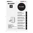
6) Key input circuit The key SW1 - SW2 on the switch PWB K is connected to the resistor R101. The key status is input into the pin 9 of the microcomputer LSI-1 via the resistor R102 and the ceramosonic capacitor C101. Key ON : H, Key OFF : L 7) LED drive circuit Repetitive signal of " H " and " L " output from the pins 18 - 20 of the microcomputer LSI-1 turns on and off the digital transistors Q110 - Q112. They are turned on one by one at intervals of certain time. When " L " is output from the pins 12 - 17 of the microcomputer LSI1 as they are turned on, the corresponding LED that are connected to them light up. The LED to display the plasmacluster mode has two colors of super-high-intensity green and blue. When in the clean mode, " L " is output from the pin 11 of he microcomputer LSI1, Q114 is turned on, and the blue LED lights up. When in the ion control mode, " L " is output from the pin 10, Q113 is turned on, and the green LED lights up. 8) Remote control recieve circuit The infrared signal transmitted from the remote control is received by the reception unit RU1. When the H/L signal is input into the pin 23 of the microcomputer LSI-1 via the resistor R81 and the ceramosonic capacitor C83, it is determined from which key the signal was transmitted. C81, C82, and C83 absorb or reduce the disturbing lights, noise derived from its own power supply circuit, and external noise. 9) Dust sensor circuit When the pulse signal, which is the dust sensor drive signal, is output from the pin 42 of the microcomputer LSI-1 (input into the pin 3 of the sensor connector CN-F), the dust sensor is activated and the sensor output signal (pin 5 of the sensor connector CN-F) is input into the pin 28 of the microcomputer (A/D conversion terminal) via R62 and C63. < Principle of dust sensor > Using the pulse signal input from the microcomputer, the infrared LED inside the dust sensor emits light. When the light is reflected by the dust that passes through the sensor, it is detected by the internal photo acceptance unit and amplified, and then output from the terminal. Receiver Luminescence side Less dust: less light acceptance less output (low voltage) More dust: more light acceptance more output (high voltage)
< Control > After turning the power on, the value obtained 20 seconds after starting the first operation (for 30 seconds, the clean sign of three colors for stabilization is lit one by one) is compared to the initial setting reference value of the microcomputer. If it is clean enough, the reference value is revised, and if it is dirtier than the designated level, the clean sign is changed to the sign that indicates the air is contaminated (orange or red, depending on the level), while the reference value remains the same. The value is compared with the reference value in the previous operation and is controlled 20 seconds or more after the operation is started. The dust sensor is always activated during operation, and air contamination is checked in every four seconds in relative comparison between the average value and the reference value. The clean sign is displayed, the fan motor is controlled or the cluster mode is switched according to the level of contamination. Reference value : If the current level is cleaner the reference valueis is changed to the current value than the reference value immediately. : If the current level is dirtier the value remains the same. than the reference value the reference value is revised when the level becomes cleaner than that. The dust sensor is activated only during the operation. It is deactivated while the operation is stopped to cut down the standby power consumption.
The hole through which dust passes
11
|
|
|
> |
|