|
Dla tego produktu nie napisano jeszcze recenzji!
 ;
Schematy są ale można wysilić się i zrobić kolorowy skan i o większej rozdzielczości. Wtedy schematy płytek będą czytelniejsze. Całość super jako wartość merytoryczna. Wszystkie dane potrzebne do podłączenia różnego rodzajów urządzeń takich gramofon, CD itd.
 ;
Szybko, sprawnie i tanio. Serwis godny polecenia. Będę polecał innym
;
Ogólnie jest OK, z wyjątkiem obrazu płyty głównej, który jest miejscami mało czytelny, ale można sobie poradzić.
;
Dokładna dokumentacja, pomogła w szybkiej naprawie telewizora. Dziękuję!
;
jedyne do czego mogę mieć zastrzeżenie to jakość zdjęć zawartych w przesłanej instrukcji serwisowej ponieważ są fatalnej jakości, praktycznie nieczytelne. tak poza tym jestem zadowolony to jest to czego szukałem.
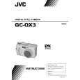
1.3.3 Disassembly method ( II ) <OP Unit>
STEP PART NAME POINT NOTE
1 OP Block ASSEMBLY 2 COVER CCD BASE ASSEMBLY SPACER SET PLATE 3 TILT FRAME RATCH GEAR MAIN PIN 4 RATCH MAGNET NUT ASSEMBLY RATCH PIECE
Remove screws 3 (208) Remove screws 3 (206),2 (207), 1 (236) Remove screws 3(206),2(207). Remove the CCD Board Assy 20(SD1) Remove the SET RING 2 (231) Remove Screws 3 (237),1 (236) Note 1 Note 2 Note 3 Note 4
Note 2 Make sure that the torsion spring is in the groove of the latch gear. Note 3 Turn the latch gear clockwise ( ) and position it so that the toothless portion comes to the level that is as high as the main frame.
NOTE2
Note 1 Turn and fix the set ring and make sure that the convex marks are identical.
NOTE3
Note 4 Never move the setscrew in the center of the nut assembly!
1
208
203
SET SCREW
208
206
2
202
206
2
234 221 222
Remove screw marks STEP 1 STEP 2 STEP 4 1 2 4
237 225
4
230 224 223
231
204 205
232 226 228 227 229 231
CCD Board Assembly
S2
SD1
207 234 236
4
233 237
4
Fig. 1-3-3
1-6
|