|
|
|
Kategorie
|
|
Informacje
|
|
Polecamy
|
|
|
 |
|
|
Dla tego produktu nie napisano jeszcze recenzji!
 ;
jedyne do czego mogę mieć zastrzeżenie to jakość zdjęć zawartych w przesłanej instrukcji serwisowej ponieważ są fatalnej jakości, praktycznie nieczytelne. tak poza tym jestem zadowolony to jest to czego szukałem.
 ;
Wszystko w porządku.
Instrukcja czytelna i kompletna.
Dziękuję.
all right!
thank you.
;
Bardzo dobra instrukcja. Zawiera wszystko co potrzeba, polecam!
;
Instrukcja jest OK. Schematy czytelne, opisane niektóre procedury.
;
Instrukcja bardzo czytelna. zawiera co potrzeba. Polecam
Connecting the Unit
Using the Speaker Input
Connect the car stereo speaker output wires to the amplifier using the supplied speaker input connector.
� Do not connect both the RCA input and the speaker input at the same time.
<ENGLISH>
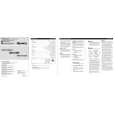
Connecting the Speakers and Input Wires
The speaker output mode can be fourchannel, three-channel (stereo + mono) or two-channel (stereo, mono). Connect the speaker leads to suit the mode according to the figures shown below. � In the case of four-channel or threechannel mode, if only one input plug is used, such as when the car stereo has only one output (RCA output), connect the plug to RCA input jack A, but do not connect a plug to RCA input jack B. � In the case of two-channel mode connect RCA plugs to the RCA input jack A.
Car Stereo
+â�
Installation
CAUTION
� Do not install in: �Places where it could injure the driver or passengers if the vehicle stops suddenly. �Places where it may interfere with the driver, such as on the floor in front of the driver�s seat. � Make sure that wires are not caught in the sliding mechanism of the seats, resulting in a short-circuit. � Confirm that no parts are behind the panel when drilling a hole for installation of the amplifier. Protect all cables and important equipment such as fuel lines, brake lines and electrical wiring from damage. � Install tapping screws in such a way that the screw tip does not touch any wire. This is important to prevent wires from being cut by vibration of the car, which can result in fire. � DO NOT allow amplifier to come into contact with liquids due to, for example, the location where the amplifier is installed. Electrical shock could result. Also, amplifier and speaker damage, smoke, and overheating could result from contact with liquids. In addition, the amplifier surface and the surface of any attached speakers could become hot to the touch and minor burns could result. � To ensure proper installation, use the supplied parts in the manner specified. If any parts other than the supplied ones are used, they may damage internal parts of the amplifier, or they may become loose causing the amplifier to shut down. � Never replace the fuse with one of greater value or rating than the original fuse. Use of an improper fuse could result in overheating and smoke and could cause damage to the product and injury including burns.
<ENGLISH>
� Do not install the amplifier on unstable places such as the spare tire board. � The best location for installation differs with the car model and installation location. Secure the amplifier at a sufficiently rigid location. � Make temporary connections first and check that the amplifier and the system operate properly. � After installing the amplifier, confirm that the spare tire, jack and tools can be easily removed.
Two-channel mode (Stereo)
Speaker (Right)
7 Connections when using the speaker input
Green: CH B, Left + Green/black: CH B, Left â�
Example of installation on the floor mat or on the chassis
1. Place the amplifier where it is to be installed. Insert the supplied tapping screws (4 � 18 mm) into the screw holes. Push on the screws with a screwdriver so they make marks where the installation holes are to be located. 2. Drill 2.5 mm (1/8 inch) diameter holes at the point marked, and install the amplifier, either on the carpet or directly to the chassis.
Tapping-screws (4 � 18 mm)
Violet/black: CH B, Right â� Violet: CH B, Right + Gray: CH A, Right + Gray/black: CH A, Right â� Speaker input connector To speaker input terminal of this unit. Speaker output
Four-channel mode
(Right) Speaker out A (Left)
+ â� â� +
Two-channel mode (Mono)
Speaker (Mono)
â�
White/black: CH A, Left â� White: CH A, Left +
(Left) Speaker out B (Right)
Three-channel mode
(Right) Speaker out A (Left)
+ â� â� +
Speaker out B (Mono)
+â�
Speaker (Left)
+
â�
+ +â� â� +
â�
Speaker (Mono)
CAUTION: To prevent malfunction and/or injury
� To ensure proper heat dissipation of the amplifier, be sure of the following during installation. �Allow adequate space above the amplifier for proper ventilation. �Do not cover the amplifier with a floor mat or carpet. � DO NOT allow amplifier to come into contact with liquids due to, for example, the location where the amplifier is installed. Electrical shock could result. Also, amplifier and speaker damage, smoke, and overheating could result from contact with liquids. In addition, the amplifier surface and the surface of any attached speakers could become hot to the touch and minor burns could result. Drill a 2.5 mm (1/8 inch) diameter hole
Floor mat or chassis
+
|
|
|
> |
|