|
|
|
Kategorie
|
|
Informacje
|
|
Polecamy
|
|
|
 |
|
|
Dla tego produktu nie napisano jeszcze recenzji!
 ;
Dokładna dokumentacja, pomogła w szybkiej naprawie telewizora. Dziękuję!
 ;
jedyne do czego mogę mieć zastrzeżenie to jakość zdjęć zawartych w przesłanej instrukcji serwisowej ponieważ są fatalnej jakości, praktycznie nieczytelne. tak poza tym jestem zadowolony to jest to czego szukałem.
;
Wszystko w porządku.
Instrukcja czytelna i kompletna.
Dziękuję.
all right!
thank you.
;
Bardzo dobra instrukcja. Zawiera wszystko co potrzeba, polecam!
;
Instrukcja jest OK. Schematy czytelne, opisane niektóre procedury.
GR-209
7. GENERAL INFORMATION
7.1 IC
� The information shown in the list is basic information and may not correspond exactly to that shown in the schematic diagrams.
M5229P (MAIN BOARD ASSY : IC2, IC3)
� Graphic Equalizer
�Pin Arrangement
IN 1 1 NF 1 2 IN 2 3 NF 2 4 IN 3 5 NF 3 6 IN 4 7 NF 4 8 IN 5 9 NF 5 10 20 �Vcc 19 GND 18 +Vcc 17 OUTPUT 16 INVERTING INPUT 15 NON-INVERTING INPUT 14 NF 7 13 IN 7 12 NF 6 11 IN 6
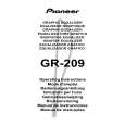
�Block Diagram
�Vcc GND +Vcc OUTPUT
NONINVERTING INVERTING INPUT INPUT
NF 7
IN 7
NF 6
IN 6
20
19
18
17
16
15
14
560
13
12
560
11
10k
10k
47k
47k
47k
47k
47k
47k
47k
47k
560
560
560
560
560
1
IN 1
2
NF 1
3
IN 2
4
NF 2
5
IN 3
6
NF 3
7
IN 4
8
NF 4
9
IN 5
10
NF 5
�Pin Function
No. 1 2 3 4 5 6 7 8 9 Pin Name IN 1 NF 1 IN 2 NF 2 IN 3 NF 3 IN 4 NF 4 IN 5 Compose the bandpass filter by connecting a capacitor with IN terminals and NF terminals located next to each other, and the gain can be set up by connecting a variable resistor (slide volume). Function No. 11 12 13 14 15 16 17 18 19 20 Pin Name IN 6 NF 6 IN 7 NF 7
Non-inverting input Inverting input
Function Compose the bandpass filter by connecting a capacitor with IN terminals and NF terminals located next to each other, and the gain can be set up by connecting a variable resistor (slide volume). Non-inverting input pin for output OP amp. Inverting input pin for output OP amp. Output pin for output OP amp. Positive power supply pin Ground pin Negative power supply pin
OUTPUT +Vcc GND � Vcc
10 NF 5
11
|
|
|
> |
|