|
|
|
Kategorie
|
|
Informacje
|
|
Polecamy
|
|
|
 |
|
|
Dla tego produktu nie napisano jeszcze recenzji!
 ;
Dokładna dokumentacja, pomogła w szybkiej naprawie telewizora. Dziękuję!
 ;
jedyne do czego mogę mieć zastrzeżenie to jakość zdjęć zawartych w przesłanej instrukcji serwisowej ponieważ są fatalnej jakości, praktycznie nieczytelne. tak poza tym jestem zadowolony to jest to czego szukałem.
;
Wszystko w porządku.
Instrukcja czytelna i kompletna.
Dziękuję.
all right!
thank you.
;
Bardzo dobra instrukcja. Zawiera wszystko co potrzeba, polecam!
;
Instrukcja jest OK. Schematy czytelne, opisane niektóre procedury.
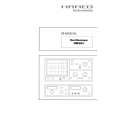
If a display is not obtained in this mode, then a lower delay time range should be selected. For example, when investigating the waveform shown in the figures, a display could not be obtained with a delay time setting of IOms, as the display is completely blanked. However, as a result of setting the DELAY rotary switch to 0.1 ps, the shifting is not visible. The DELAY range switch should then be rotated clockwise until the display starts just prior to the short time interval to be investigated. The precise adjustment to the start is done with the VAR. 1O:l delay time control. The rotating range of the latter has no stop. On the range limits a certain snapping noise is audible. Initially, this control should be set in the left start position. In the SEARCH mode, the LED indicator will flash.
Figure 2
If the timebase sweep speed is increased (rotate TIME/ DIV. switch clockwise), then the short time interval will be expanded. It may be found that, as the amount of expansion is increased, the trace will tend to shift. If this happens, the VAR. delay time control can be readjusted - also subsequently at any time - to enable the exact point of interest to be displayed. In the example shown in figure 4, it can be seen that an expansion of x10 was obtained by increasing the timebase sweep speed from O.Sms/cm to 5Ops/cm. Also the precise measurement for the delayed portion of the waveform is possible. In the example, this was found to be 250~s on multiplication of the horizontal length in cm (of an optional signal section) by the time coefficient just adjusted.
Figure 4
MODE DELAY range TIME/DIV. LED
Delay time = 2.5cm
: SEARCH :lms : 0.5 mskm
T= 1.25ms
: flashing . 0.5mskm
In figure 2 it can be seen that the delay time is also measurable as the blanked portion or apparent shift of the start of the trace. This time can be determined by multiplication of (the horizontal shifting in cm) by (the time coefficient set on the TIME/DR!. switch). Now the mode switch can be set to DELAY. In this mode, the LED is permanently illuminated. The display will now shift to the left and the trace will commence in the same position as for a normal display; however, the short time interval under investigation now starts on the first or left vertical graticule line.
Figure 3
MODE DELAY range TIME/DIV. LED
Expansion
: DELAY :
:lms : 50 @cm
illuminated :o.5~10-3:50~10-6=10
T = 5cm. 50@cm = 250~s
Operation of the sweep delay requires a constant trigger point. All signals, which have a constant phase shift between the expanded section and trigger point, pose no problems. This means all electrical signal shapes, which contain signal edges of the same polarity and with triggerable level values, which are constantly repeated with the recurring frequency. If there is no constant phase shift, the triggering may fail after switching from the SEARCH to DELAY position or with changing of the time coefficient. It is best to attempt to find a trigger point, which has a constant phase shift up to the signal section to be expanded in the OFF mode. With complicated composite signals, the display of the basic period could become superimposed by other signal portions. These dissappear as a rule when the sweep is increased. Otherwise, a stable expanded display is obtained by adjusting the LEVEL and the variable sweep control or by means of the HOLD-OFF control. Using the X MAG. x10 button, a tenfold expansion of the
MODE DELAY range TIME/DIV. LED
: :
DELAY
:lms : 0.5 ms/cm
illuminated
desired signal section is possible without any change of triggering or timebase. This can be of assistance with complicated or difficult-to-trigger signals.
Subject to change without notice
Ml4 604
|
|
|
> |
|